 |
This task shows you how to replace
a plate in a mold. A mold is an assembly composed of a pile of plates.
Those plates can be split by a surface and drilled by some components.
The
coherence of the dimensions and positions of the different plates within the
mold is maintained by some relations and some constraints.
In some cases, you will need to replace one plate by another.
A typical
example is a process of iterative design where a simplified version of a
plate is replaced by a more advanced version.
Since the plates are linked to
the other parts of the assembly by many objects such as constraints,
relations, contextual imports, etc, replacing a plate by another is a very
complicated operation.
Moreover the Tooling Feature extensions of tooling
components add some links in the products structure that can be corrupted if
you try to replace a plate “by hand”.
The Replace Plate command:
- keeps the same feature extension on the new plate,
- re-creates the relations that define the dimensions of the plate
(Width (W), Length (L), Height (H)):
the replacing plate size is adjusted to the mold
dimensions,
- in the case of a standard Mold Base, the replacing plate must be a
plate of the same Mold Base catalog:
the Replace Plate command
will set the value of the Ref parameter of the replacing plate to that of
the replaced plate.
- reconnects the constraints: constraints with the other plates,
constraints with the components,
- reconnects automatically the link to the splitting surface of the
replaced plate if any,
- proposes a manual reconnection for the external references of the
replacing plate that have not been automatically reconnected
- re-creates the drillings of the replaced plate inside the replacing
plate (Standard drillings, detailed drillings and Coolant Channel),
- re-creates the simplified drillings,
- propagates the machining attribute, colors and Technological Results
from the drilling components to the drillings in the replacing plate,
- reroutes the links of the feature extensions of all the Tooling
Components that drills the plate.
|
 |
Please note that:
- The Replace Plate command only applies to a Mold Tooling
Design plate (CATPart that has a Mold Tooling Design Plate icon).
- This command can only be used to replace a CATPart by another CATPart.
You are not allowed to select a CATProduct as the replacing plate.
- The replacing plate must contain the PLRef plane and the ZRef,
L, W
and H parameters.
- If some features such as fillets or chamfers have been added on the
top of drillings made by tooling components in the plate, those features
will not be re-created in the replacing plate.
- Drillings performed without using Mold Tooling Design dedicated
commands will not be automatically re-created in the replacing plate.
- If the replaced plate is split and if the replacing plate is not
split, the split of the replacing plate is not re-created.
|
 |
Open the MLDwithPlateToReplace.CATProduct
from the samples\ReplacePlate
directory. |
 |
-
You are going to replace the top plate.
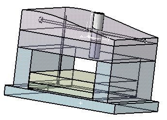
Pick it in the 3D
Viewer and select Replace Plate in the contextual menu.
This
menu is also available from the specification tree.
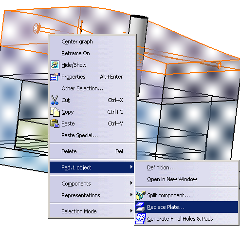
The Replace Plate dialog box is displayed.
The name of the
plate to replace is displayed in the title.
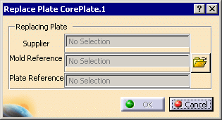
-
Click
 to browse your directories and select ReplacingCorePlate.CATPart in the
samples\ReplacePlate directory.
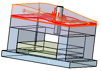
The dialog box is updated with information about the replacing plate. They
are not editable.
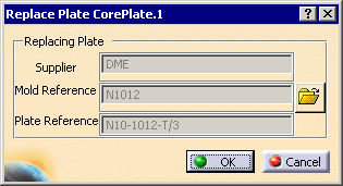
A preview of the replacing plate is displayed.
Its H, L, W parameters are
set to the values of the corresponding parameters of the replaced plate.
If the MoldBase is a standard Mold Base, the Ref parameter of the
replacing plate is set to the value of the Ref parameter in the replaced
plate (same line in the Design Table). This way the overall consistency of
the mold base is preserved.
|
 |
-
If the PLRef plane or the ZRef parameter, or the
L, W or H
parameter are missing in the replacing plate, an error message is
displayed asking you to select another plate or to define the missing
parameter.
-
If the Mold Base is a standard Mold Base, the command searches the matching configuration (RefMold,
Ref) in the design table of
the replacing plate. If no matching configuration is found an error
message is displayed asking you to select another plate.
-
The dialog box is updated and the preview performed once a
valid replacing plate has been selected.
|
|
|
-
Click OK.
If some external references could not be
reconnected automatically, the following dialog box is displayed to let
you reconnect them manually:

Select a line, the buttons on the right becomes available.
According to
your need, click Isolate, Reconnect or Delete.
Click OK when you are done.
-
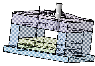
The original plate is replaced by the new one, as
described in the introduction above.
Its length, width and height are those of the replaced plate.
In the case of a standard Mold Base, the Ref parameter (and thus the
active line of the Design Table) takes the value of that of the replaced
plate.
The part number of the replacing plate is that of the replaced plate.
|
|
 |
![]()