 |
This task shows you how to create a mold base from a
catalog. |
 |
Open the
Snap.CATProduct from the Snap directory in the samples directory.
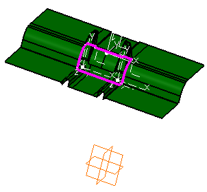
Display the xy, yz and zx planes (using Hide/Show
in their contextual menu) and compare this axis system with that of the main
pulling direction of the part (in orange). You can see they are different.

|
 |
-
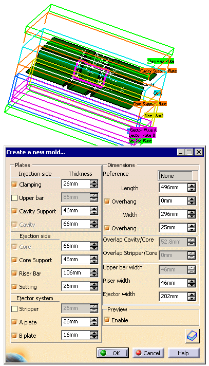
Click Create a new mold
 . The Create a new mold
dialog box is displayed, and the mold is pre-visualized around the molded
part. . The Create a new mold
dialog box is displayed, and the mold is pre-visualized around the molded
part.

|
 |
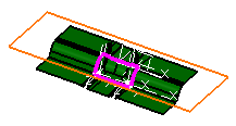
Note that the pre-visualization is done into the molded part position
and orientation. |
| |
-
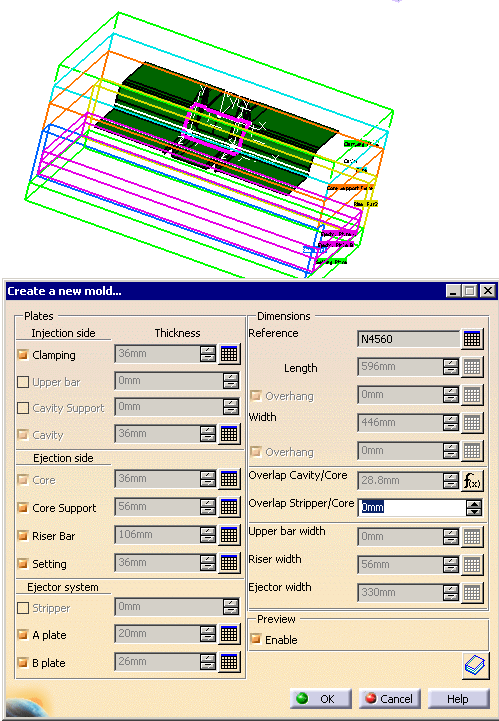
In the New
Mold dialog box, click the catalog icon
 to access the catalog
browser. to access the catalog
browser.
The mold pre-visualization is erased and the catalog browser is displayed.
-
Double-click the name of the supplier you want to select
(Dme, Eoc, Hasco, etc.) to visualize a pre-display of the mold base in the
top right window.
|
 |
Note that a rectangle is displayed in the viewer showing
you the width and the length of the reference you have selected.
 |
| |
-
Double-click a reference to revert to the first dialog box
of the dialog box to customize it, if necessary.
 -
Click OK to create the mold. The molded part
has been snapped in the right orientation and
located in a middle position between cavity and core plates.
|
 |
- By default, the mold is created in the axis system of the main pulling
direction. You could have picked another axis system to orient the molded
part.
- The InjectionSide, the EjectionSide and the EjectorSystem are now
created as CATProducts. This way, they can be edited separately.
|
|
 |
![]()
