- the rough stock
- the part to machine and the associated bottom and imposed planes.
Creating the rough stock
-
Go to the Geometry Management tool bar and pick the Creates rough stock icon
 .
. -
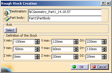
The Create Rough Stock dialog box is displayed.
Select NCGeometry_Part1_14.18.57 as the Destination and pick the part
to fill in automatically the Definition of the Stock fields.
-
Click OK, the Rough stock is created in the specification tree.

Defining the geometry for the operation
-
In the Multi-Pockets Operations toolbar, pick the Power Machining icon

-
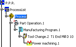
Select ManufacturingProgram.1 in the specification tree.
A Power machining.1 operation is created in the specification tree.
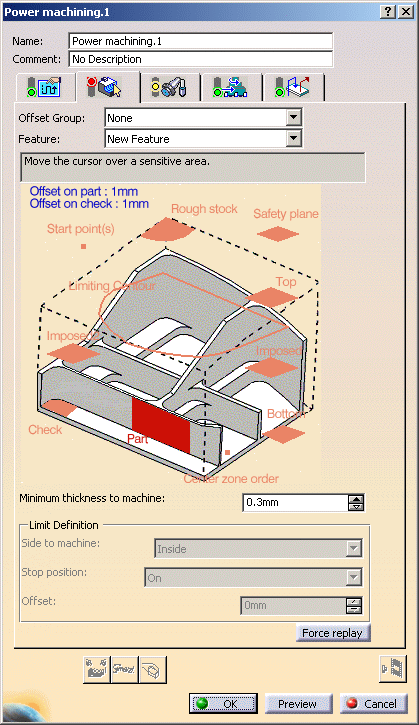
The Power machining dialog box opens.
The sensitive area Part is red, which indicates that you must select a part to machine.
The other definitions are optional.
If necessary, hide the rough stock or the reference planes to make picking easier).
-
Pick the sensitive area Part. The dialog box shrinks to allow you to select the part in the viewer.
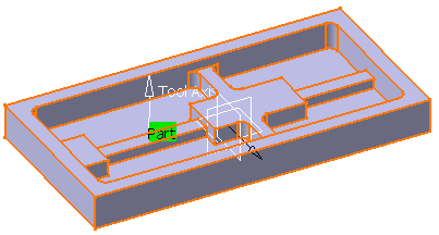
In the viewer, pick the part.
-
Double click anywhere in the viewer to confirm your selection and to redisplay the dialog box.
The red area Part is now green to indicate that the geometry has been selected. -
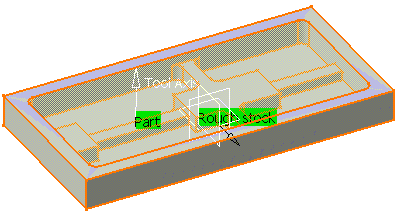
Pick the sensitive area Rough stock and select the rough stock in NCGeometry_Part1_14.18.57.
You may then hide it for an easier selection of the geometry.
-
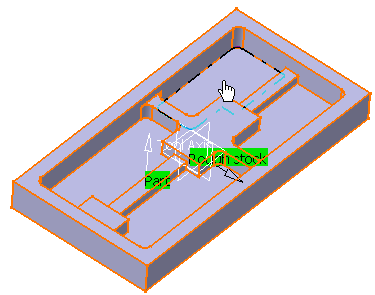
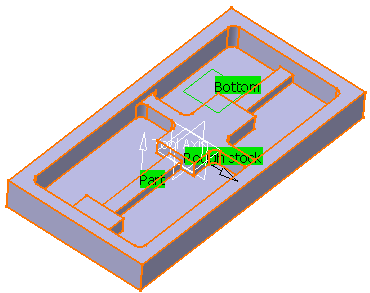
Pick the sensitive area Bottom and select the geometry as shown.
The sensitive area Bottom turns green.
-
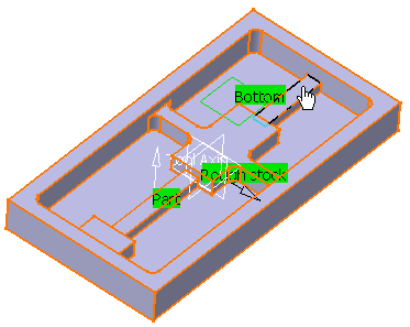
Pick one sensitive area Imposed and select the geometry as shown:
-
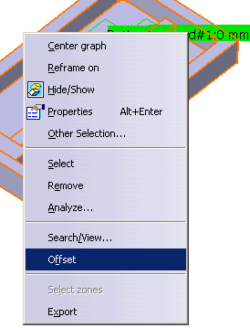
Use the Offset contextual menu item to set an offset on this plane.

-
Now pick the other sensitive area Imposed and repeat the step above with the following plane:

-
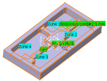
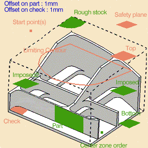
Pick Center zone order and define in which order the center zones are to be machined.
You have the following result:
-
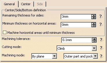
In the Machining strategy tab, make sure the Machining mode is set to By plane and Outer part and pocket.
-
Leave the options at their default values and push the Tool Path Replay button, then OK twice.
A Power machining.1 operation is created in the specification tree.
![]()