 |
This task illustrates the
associativity of prismatic machining areas. A prismatic machining area in
the manufacturing view has associated geometry in the part document.
Typical geometry could be:
- Top element
- Bottom element
- Boundary profile
- Other Prismatic machining area parameters such as minimum corner
radius.
If the geometry is modified in the part document, then corresponding
parameters and RSUR information for prismatic machining area is updated in
manufacturing view to reflect correct values. |
 |
1. |
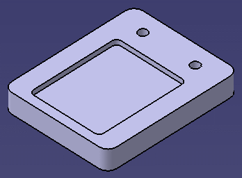
Select File > Open then select the
PrismaticMachining.CATPart
document. |
|
2. |
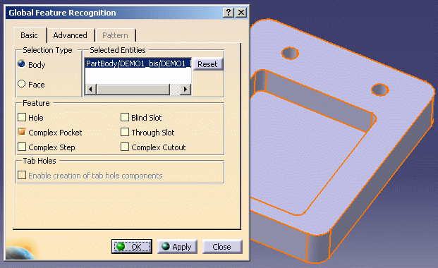
Select the Global Feature Recognition icon
 and create a Complex Pocket.
 |
| |
3. |
Select the Manufacturing View icon
 in the Machining Features toolbar. Right-click the Manufacturing View
object and select the Sort by Machining Features contextual
command.
|
| |
4. |
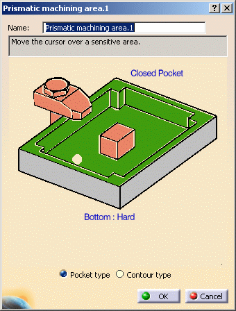
Double click the created Prismatic machining area in the
tree. A dialog box appears showing the characteristics of the feature.
 |
| |
5. |
Right click the green flank area of the pocket in the
sensitive icon and select the Analyze contextual command. The Geometry
Analyser appears showing that the status of each of the guide elements
making up the pocket is Up to date.

Analyze the bottom element in the same way to check that its status is
also Up to date.

|
| |
6. |
Modify the geometry of the pocket (for example by reducing
the pocket depth). 
|
| |
7. |
In the Manufacturing View, analyze the new guide elements
and bottom of the pockets.


Their status is Up to date, showing the associative nature of the
prismatic machining area. |
 |
|
Some geometry modifications to a part document can change
the feature type. For example:
- the depth of complex pocket can be changed so that it becomes complex
cutout
- the boundary profile of a complex pocket can be modified in such a
way that it becomes a complex step, blind slot or through slot.
Such changes are not associative. |
|
 |


![]()