-
Select the Multi-Axis Contour Driven icon
 .
.
The Multi-Axis Contour Driven dialog box appears directly at
the Geometry page  .
.
-
Right click the red Part area in the icon and
choose the Select faces contextual command.
The Face Selection toolbar appears.
Select the face to be machined and click OK in the toolbar.
-
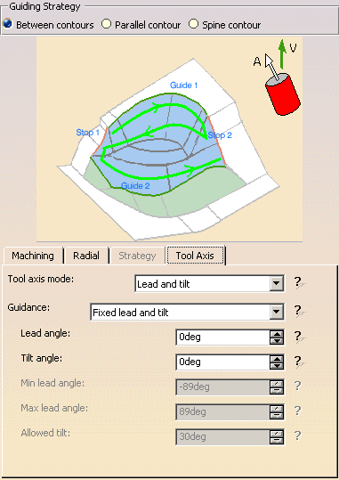
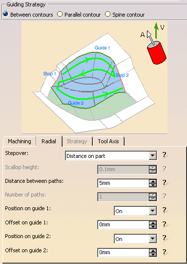
Select the Strategy tab page
 and set the
parameters as shown.
This operation will use a Between Contours strategy and the
tool axis will be guided in Fixed Lead and Tilt mode.
The other parameters are the same as the previous operation.
However, in the Radial tab page you can set the Stepover
strategy to Distance on Part.
-
Click the View Direction arrow (V) and set
the view direction to (0, -1, 0) in the dialog box.
-
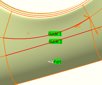
Click the red Guide 1 curve in the icon then
select the first guide curve in the model.
Click the red Guide 2 curve in the icon then select the
second guide curve in the model.
-
Select the Tool tab page
 .
.
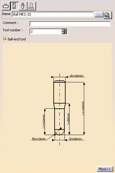
Enter a name of the new tool (for example, Ball Mill D 20).
Select the Ball-end tool checkbox.
Double click the D (nominal diameter) parameter in the icon,
then enter 20mm in the Edit Parameter dialog box.
Set the db (body diameter) parameter to 24mm in the same way.
-
Click Tool Path Replay in the dialog box to
visually check the operation's tool path.
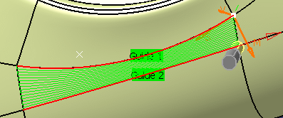
-
Click OK to exit the replay mode and return to the
Multi-Axis Contour Driven dialog box.
-
Click OK to create the operation.


