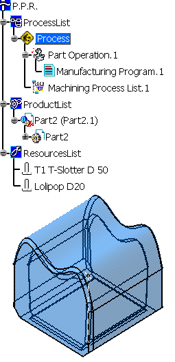
-
Click Multi-Axis Tube Machining
 .
.
The Multi-Axis Tube Machining dialog box is displayed.
-
Go to the Tool tab and select the tool
Lollipop D20.
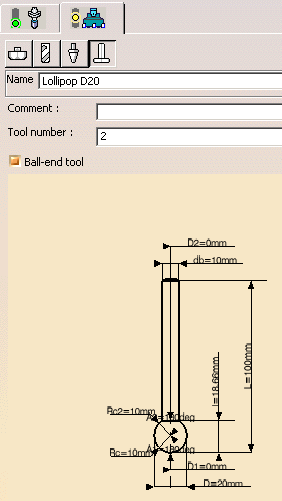
-
Go to the Geometry tab and select Body.2 as
the Part:
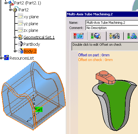
-
Go to the Machining Strategy tab.
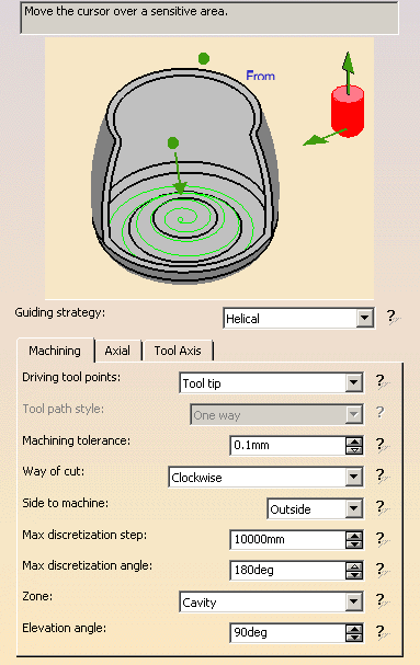
Set the Guiding strategy to Helical.
In the Machining tab,
set Driving tool points to
Tool tip,
Side to machine to Inside and
Zone
to Cavity.

-
Go to the Tool Axis tab.
Set Tool axis
mode to Thru a point and change From to
To.

Select Point.2 as the Axis Point.
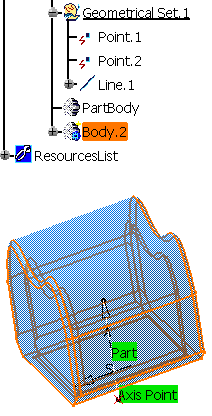
-
Right-click the axis in the graphic icon and
select
As guiding axis in the contextual menu.
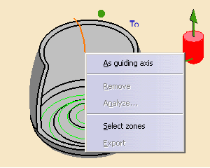
The graphic icon turns to:
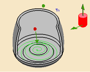
Click the red dot and select Point.1. This point is taken as the center
of the cavity to machine.
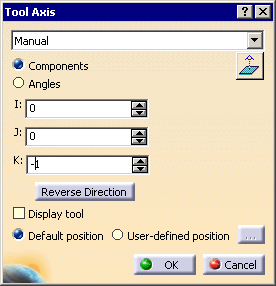
Click the arrow representing the tool axis and set the tool axis as
shown below:
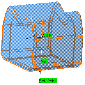
The tool axis A (black arrow) specifies where the cavity is located.
the Machining direction M (orange arrow) specifies that the machining is
performed from bottom to top.
-
Click Tool Path Replay. The Tool Path is
displayed:

Click OK. Multi-Axis Tube Machining.1 is created
in the specification tree.
-
Copy Multi-Axis Tube Machining.1 and edit it:
Change its name to Multi-Axis Tube Machining.2,
Set Side to machine to Outside,
change To to From,
select Line.1 as the guiding curve and
reverse the tool axis.
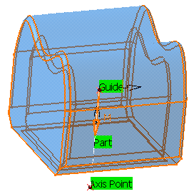
Note that the center of the cavity is one of the end points of the
guiding curve.
If you define a relimiting point, this point will become the center of
the cavity.
Click Tool Path Replay. The Tool Path is
displayed:
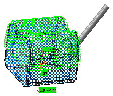
Click OK. Multi-Axis Tube Machining.2 is created
in the specification tree.
