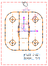
Open the Views.CATDrawing document. This drawing contains front, left and top views.
-
From the drawing window, select Tools > Export to Layout View.
-
Select a view, either from the specification tree or from the drawing sheet. For example, select the front view.

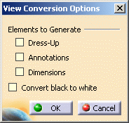
The View Conversion Options dialog box is displayed.

-
Optionally select the Dress-Up, Annotations and Dimensions options to generate these elements in the layout.
-
Select the Convert black to white option, to generate elements (dress-up, annotations, dimensions and geometry) using the white color in the layout if they are black in the drawing: this will allow you to see them better.

If the original drawing elements are in a color other than black, this color is maintained for the generated 3D elements. -
Click OK.
-
In the layout window, select the empty sheet either from the specification tree or from the geometry area.
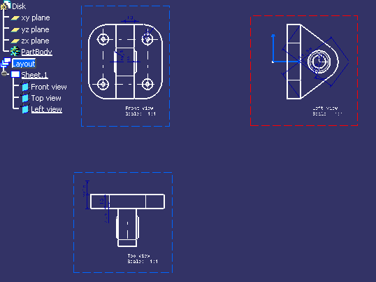
The front view is created in the layout sheet and listed in the specification tree. -
Repeat steps 1 to 6 to export the top and left views from the drawing to the layout.
All views are created on the layout sheet (with their dress-up, annotations and dimensions if you generated them) and they are listed in the specification tree.
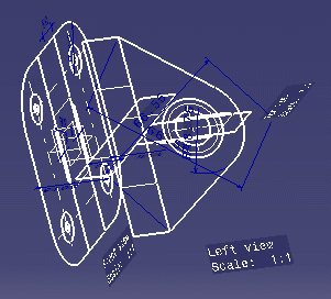
If you now switch to the part window, you can see how the layout is previewed.

More about exporting a drawing view to a layout
When exporting a drawing view to a layout, remember the following points:
- You cannot export generative views (generated from the 3D via the Generative Drafting workbench) to a layout sheet unless you isolate them first. In other words, you can only export interactive views or isolated generated views.
- Whatever their original type, all exported views are created as auxiliary views in the drawing, even though they keep the same name. For example, a left view in a layout sheet will still be called left view in the drawing but will be an auxiliary type view.
- As it is not possible to create any geometry in a product document, you cannot export a drawing view to a layout stored in a product document. You can only export a drawing view to a part layout.
- You can only export to a layout sheet the drawing view types listed
below:
- Front, Left, Right, Top, Bottom, Rear and Auxiliary View
- Isometric View (no geometrical element will be visualized in the 3D window)
- Isolated Section View and isolated Section Cut.
You cannot export any other view type than those listed above, and you cannot export views in detail sheets.
- The position in 3D space of layout views thus generated is implicitly defined by the drawing view.
- You cannot export a drawing view to a layout detail sheet.
- You cannot export to a layout sheet any image contained in the drawing. Drawing views containing images will be exported without these images.
- The generated layout elements (dimensions, annotations and dress-up) are represented according to the standard used by this layout, independently of the standard used by the drawing. In other words, some elements may be visualized differently in the layout and in the drawing if they use two different standards.
- The graphic properties applied to dimensions, annotations and dress-up are preserved at export (with the exception of the color which can be set to white if the original drawing element is black and you select the Convert black to white option when exporting).
- The graphic properties applied to geometry (color, pickable, Low/High Int, line type, line thickness) are preserved at export (with the exception of the color which can be set to white if the original drawing geometry is black and you select the Convert black to white option when exporting).
- Dimensions and annotations remain associative to geometry (positional and orientation links) at export.
More about exporting 2D components
The resulting view and its sub-elements do not keep any link to the original document: in particular, if the original view contains some 2D component instances, the whole 2D component structure will also be imported in the target drawing or 2D Layout. In this case, the service searches for all the required 2D components recursively, by identifying if they have to be imported at the same time.
The algorithm to identify if a 2D component has to be imported is based on an identification by its name:
- if a 2D component with the same name and sheet name is found in the target document:
- this 2D component will not be imported
- all the 2D component instances of this 2D component will become instances of found 2D component, no matter what its content or synchronization status is.
As a consequence some detail sheets may be created during the import.
- If no 2D component with the same name and sheet name is found, the 2D component reference will be imported in the target document.
If a required 2D component is not located in the
original document (for example a 2D component instance coming from a
catalog), the import process will fail if the other document is not
accessible. In addition, if the original view contains texts with
attribute links, those texts are isolated (it includes the view name
text). |
Associative annotations and dimensions
If some annotations or dimensions are associated to any 2D component instance (in the view or any 2D component that will be imported), for example a leader with positional link to a 2D component instance sub-element or a dimension on a 2D component instance sub-element, this association will be lost in the target document. This is a limitation.
|
|
As the target drawing and 2D Layout may use a different standard, the graphical result of some annotations or dimensions may differ between the original document and the resulting view, with respect to the target document standard. |
View type
The resulting view type does not depend on the original view type: it is always created as an auxiliary view. However, if the specified view:
- is a 2D component view: the resulting view may be a 2D component view, as soon as the target sheet is a detail sheet.
- is not a 2D component view: the 2D component view is imported as an auxiliary view in a design sheet. In addition, the view axis is the same as the original view.
![]()