In the Visualization toolbar, activate the
Display Backgrounds as Specified for Each View
![]() icons.
icons.
-
Double-click the section view to activate it.
-
Click the Intersect 3D Elements icon
 in the 3D Geometry toolbar (Use-edge sub-toolbar).

-
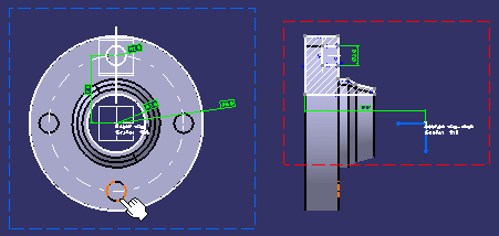
Select the element to be intersected. For the purpose of our scenario, select a pocket from the circular pattern in the 3D background of the front view.

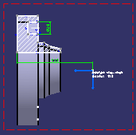
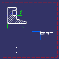
The intersected geometry is created onto the section view plane.

-
Optionally, deactivate the Display Backgrounds as Specified for Each View
 icon to view the projected silhouette edge without the 3D background.
More about intersecting 3D elements
When intersecting 3D elements, remember the following points:
- The element to be intersected can be either a body, a surface/solid feature in a body, a face or an edge.
- Selecting a body or a feature results in selecting its constituent faces.
- The intersected geometry is created in the current view.
- If the selected element is invalid or if no intersection is found, an error message is displayed.
- Be careful when multi-selecting a mix of 2D and 3D elements to intersect. In this case, 2D elements are intersected only if they are located in the view background; in other words, any 2D element located in the foreground of the view will not be taken into account.
- In certain cases, the object to be intersected (often a face) may be
perpendicular to the current view, and may be seen as "degenerated", in
which case you may have difficulty selecting it.
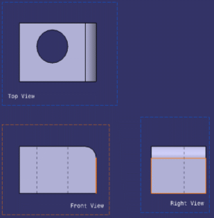
In such a case, you may select that object from a different view. As shown below, for example, you could select a face in the right view (non-current view) to create an intersection (a line in this case) in the front view (current view).

- When the selected element is a face with planar geometry, the
following cases are possible:
- If the face is not parallel to the view plane and the intersection is found inside the face topology: the result is a limited line, which is identical to the result of the face intersection.
- If the face is not parallel to the view plane and the intersection is not found inside the face topology: an infinite line is created as the result of the two infinite planes. Note that in this case, the created line is a construction element.
- If the face is parallel to the view plane: no element is created.