| When you create a new turning operation, you can generate geometry from
the previous operations in your program then use that geometry as stock for
the new operation. This is done using the
Update Input Stock command in the machining operation
editor. The Stock computation is done before you select geometry (stock or
part) in your new operation. It creates a sketch that highlights the
remaining material on the part. The computation takes into account all
complete operations in the program before the one being edited.
Stock computation is based on the stock solid specified in the Part
Operation dialog box. The primitives of the material removed by each
previous operation are subtracted from this stock. The removed area
computation takes the parameters of the machining operations into account.
Stored or locked tool paths are not taken into account.
The result of the computation is a sketch which contains the view of the
remaining material in the working plane.
The operations taken into account for Stock computation are:
- Rough Turning
- Groove Turning
- Recess Turning
- Profile Finish Turning
- Groove Finish Turning
- Sequential Turning
- Ramp Rough Turning and Ramp Recess Turning
- All Drilling operations along the spindle axis.
Thread Turning operations are not taken into account.
Defining the Machine and Stock
Firstly, you need to define a stock and a lathe machine on the Part
Operation.
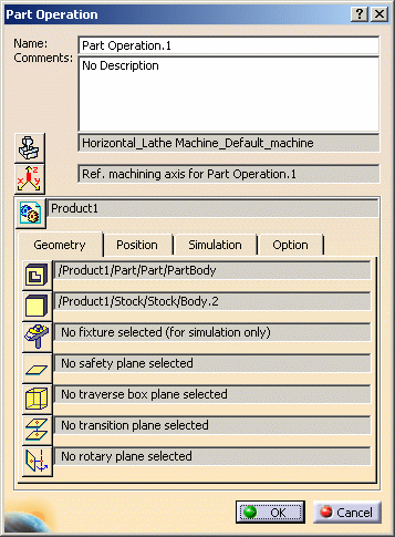
Double-click the Part Operation in the tree to display the Part
Operation dialog box.
Click the Machine icon in the dialog box the select a horizontal lathe
machine. You must set up the spindle and radial axes correctly (that is,
spindle to Z and radial axis to X in this example).
Click the Stock icon then select a solid representing the stock.
Double-click on the background to leave the geometry selection mode.
The dialog box is updated with the name of the selected machine and
stock.
Note:
The generation of the stock is based on In Process Models (IPM).
For each stock part specified in the Part Operation dialog box, an IPM
will be generated. The name of the IPM part will be the same as the
reference stock part name with the prefix "IPM_". The IPM part will be
created in the same location as the corresponding design part (the design
part is considered instead of the stock part because often the stock part
is just a body inside the design part).
For file system users, this means that the CATProduct that contains
the design part will be modified with the addition of the IPM CATPart
(under the root node of the CATProduct).
The CATProcess must be linked to a CATProduct that include the
design part. The input stock calculation cannot be done if the CATProcess
is not linked to the CATProduct.
The IPM CATPart is dedicated to the input stock calculation. No other
geometry must be created in this CATPart.
For PPR hub users, the IPM CATPart is inserted under the "Subassembly"
node of the corresponding design part.
Computing Stock
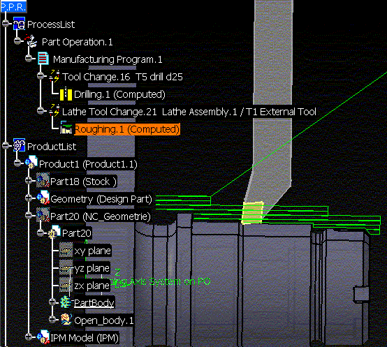
The following figure illustrates Stock computation after a Drilling
(along the spindle axis) and a Roughing operation. Here is the tool path of
the Roughing operation:
When creating a new Roughing operation after Roughing.1, click the
Update Input Stock icon
 in
the dialog box of the new Roughing operation. in
the dialog box of the new Roughing operation.
The following figure shows the result of the computation. The Stock has
been created in orange. It is located in a sketch whose identifier is the
name of the last operation taken into account for the computation
(Roughing.1) plus the item StockSketch and the time of the computation.
The Stock sketch has been created in a body with the same name, in a
part named IPM_xxx (where xxx is the name of the selected stock solid). The
part is located in a product with the same name.
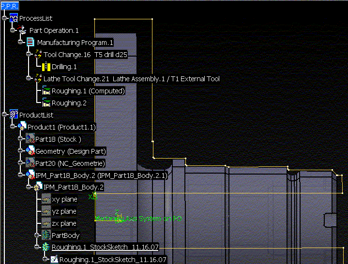
You can now select elements of the Stock sketch as new Part or Stock of
the Roughing.2 operation.
Stock Sketches, IPM Bodies and Primitives
The Stock computation automatically creates an IPM body (CATPart).
In order to create the Stock, some primitives are created in the IPM
body. Once the stock sketch is created, the sketch is no longer linked to
them.
The sketch of the input stock is linked to the operation. When editing
the operation the sketch is in Show mode. When the operation editor is
closed, the sketch is in Hide mode.
By right-clicking the Input stock status field in the
Geometry tab page of the operation editor, it is possible to remove the
stock sketch. In this case the sketch is deleted.
A primitive is created for each Turning operation. Each primitive takes
the machining paths of the tool trajectory into account.
If you use the Stock computation again, the existing primitives will
speed up the computation. They will be used if the operations to which they
are linked have not been modified since the Stock computation. Otherwise
they will be modified.
If you have finished your Part Operation, you can remove these
primitives by using the Clean Computed Stock Data contextual
command on the Part Operation. This command removes each primitive of the
IPM body linked to the operations in the Part Operation. It does not
remove the Stock sketches or the IPM body.
For a CATProcess created in a previous version, the previous IPM body
will be migrated automatically. An IPM CATPart will be created for each
solid selected as stock.
Considerations for Machining Local Recesses
The Update Input Stock functionality is best suited to
operations in which the stock is to be updated globally.
For a local recesses or grooves like the one shown below, you may be
advised to update the input stock manually.
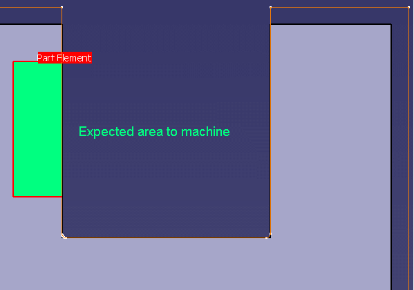
For example, the expected area to machine (in green) above may be
interpreted by the program as the area to be machined (in green)
below.
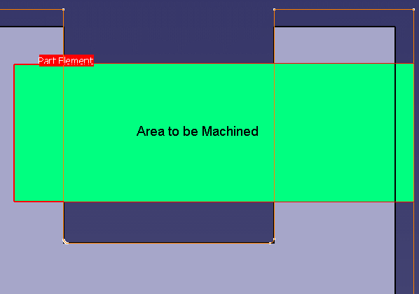
This is due to the ambiguity that arises due to the shape the selected
stock profile.
Stock Computation: Hybrid Bodies in the IPM Part
From V5R14 on, bodies that are created automatically when computing the
stock in the IPM part are hybrid, unless the Enable hybrid
design option is unchecked in Tools > Options > Infrastructure > Part
Infrastructure > Part Document (in that case, created bodies are
non-hybrid).
It is recommended not to mix Hybrid and non-hybrid bodies in the IPM part,
otherwise some incorrect coloring of faces of the IPM will occur.
If the IPM part was created before V5R14, then the Enable hybrid
design option should be unchecked, so that the IPM part will contain
non-hybrid bodies only.
If the IPM part was created from V5R14 on, the Enable hybrid design
option should remain selected (this is the default), in order to have
hybrid bodies only in the IPM part. |