|
-
From the Start>Mechanical Design menu, access
the Part Design workbench.
-
Click the Sketcher icon, the xy plane, and
create a rectangular sketch.
-
Create a parameter of Length type.
-
Click the
 icon.
icon.
-
Select Length in the scrolling list to define the
type of the parameter, click New parameter of type,
change the name of the parameter (Distance_To_Axis in this
scenario), and set its value to 0mm. Click OK.
|
-
Create a constraint on the Distance_To_Axis parameter
that will define the distance between the left vertical edge of the
sketch and the VDirection-AbsoluteAxis.
-
Double-click the digital value of the constraint,
right-click the Value field, select Edit formula..., and enter
PartBody\Sketch.1\Offset.5\Offset
= Distance_To_Axis by selecting Distance_To_Axis in the specification
tree or in the Member of All window. Click OK
twice.
-
Close the sketcher and create a pad by clicking the Pad
icon ( ). ).
-
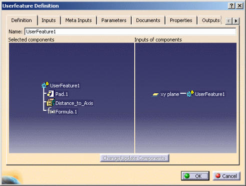
Create the user feature.
|
|
|
|
|
 |
-
Publish the Distance_To_Axis parameter.
To do so, select the Parameters tab, select the
Distance_To_Axis parameter in the Available parameters
column to publish the Distance-To-Axis parameter.
Check the Published Name check box, rename the parameter
(Axis in this scenario).
|
-
Select the Type tab, and, in the
Super Type field, click Auto. MechanicalFeature is
displayed.
In the Type1 field, enter UDF1 and click Generate.
|
-
Click OK to close the Userfeature Definition
window: a UDF is added to the KnowledgeTemplates node.
-
Add a new body to the CATPart file. To do so, access the
Part Design workbench and go to Insert>Body. Rename the
inserted body (Result_Body in this scenario).
-
Access the Knowledge Advisor workbench.
-
Click the Loop icon.
 |
The Loop function enables you to instantiate a UDF in
its creation CATPart. |
-
Click the Context field and select
Result_Body in the specification tree.
-
Select UDF1 in the specification tree. UDF1 is displayed
in the Name field.
-
In the From field, enter 1 and enter 4 in the
To field.
-
In the Loop editor, enter the following script.
UDF_$i$ isa UDF1 // UDF1 is the name assigned to the UDF

             {

             Axis = 120mm * $i$; //Name of the published parameter

} |
 |
In the script above, the UDF is instantiated by
using the user type. |
-
Click OK: the UDFs are instantiated in the
CATPart. 4 pads are displayed: the one you created and the 3 instantiated
ones.
-
Access the Knowledge Expert workbench.
-
Click the Expert Check icon ( ),
rename the check, select the KWE language, and click OK. The
Check Editor opens. ),
rename the check, select the KWE language, and click OK. The
Check Editor opens.
-
Enter the following script in the editor, then click
Apply and OK.
|

|
udf1:UDF1 // UserFeature1 is the instance you indicated
Step 10 |
| Editor |
Message("#", udf1.Axis) /*Axis is the name of the
published parameter*/ |
-
Click the Solve icon ( ).
A message box displays the distance to axis of each UDF. ).
A message box displays the distance to axis of each UDF.
 |
The types generated when creating the UDF appear
in the Object Browser (of the Expert Check Editor and of the Expert
Rule Editor) in the package you selected in the Manage Type
window. |
|
![]()
![]()