Within DMU Kinematics Simulator workbench, you can generate a certain number of features (specific to DMU Kinematics Simulator application or not specific). They are identified in the specification tree as icons under the Application node. The following image is not exhaustive but gives you an idea of what you can obtain:
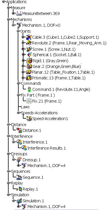
Icons displayed in the specification tree and specific to the DMU
Kinematics workbench identify:
|
|
mechanisms |
|
|
Fixed part |
|
|
command |
|
|
speeds and accelerations |
|
|
dressup |
|
|
revolute joint |
|
|
prismatic joint |
|
|
cylindrical joint |
|
|
screw joint |
|
|
spherical joint |
|
|
planar joint |
|
|
rigid joint |
|
|
point curve |
|
|
slide curve |
|
|
roll curve joint |
|
|
point surface joint |
|
|
U joint |
|
|
CV joint |
|
|
gear joint |
|
|
rack joint |
|
|
cable joint |
|
|
joint using axis system |
Other icons (which are not specific to DMU Kinematics):
|
|
Distance and band analysis entries |
|
|
Measures made using the Measure Between command |
|
|
Clash entries |
|
|
For more information about icons specific to DMU Space Analysis workbench, refer to Specification Tree section in the DMU Space Analysis User's Guide |
|
|
simulation entries ('Fitting' simulation) |
|
|
Replay entries |
|
|
sequence entries |
|
|
Laws |
![]()
For standard specification tree symbols, see
Specification Tree Symbols in the Product Structure User's Guide.