![]()
Open Auto_reconnect.CATProduct document.
![]()
When you create joints, you can define the mechanism within the same dialog box. Remember though, that you create a mechanism independently from the joints by selecting Insert > New Mechanism... from the menu bar.
Automatic switch to Design mode:
If you work with the cache system in visualization mode, you no longer need to use Edit > Representations > Design Mode beforehand as the switch to design mode is automatic (an eye appears as you point the product in the geometry or specification tree). All you need to do is click.
-
Check the mechanism can be simulated, for this: click Simulation with Commands
 in the Simulation toolbar.
The Kinematics Simulation dialog box appears.

Note: the state of the dialog box depends on your settings (expanded or not)
The command of the kinematics mechanism are available as shown below.
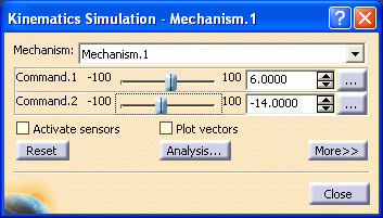
-
Run your simulation using the sliders corresponding to the commands. The pointer can move along the pad surface.
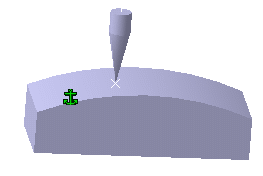
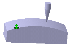
-
Click the
 button and when done, click Close.
 -
In the specification tree, double-click the Hole feature under Pad Surface node.
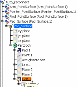
-
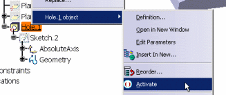
Right-click Hole.1 and select Activate from the contextual menu displayed
The hole appears on the surface:
The Part Design workbench is open.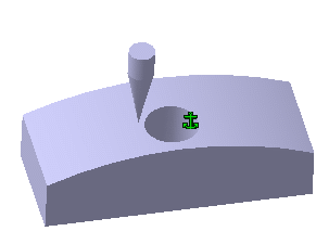
-
Select the Auto_reconnect product in the specification tree to switch back to Kinematics Simulator workbench.
-
Click the Simulation with Commands icon
 in the Simulation toolbar.
 -
Run your simulation using the sliders corresponding to the commands. The pointer can move along the pad surface.
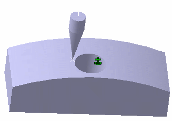
The mechanism can be simulated taking into account the added hole.
The point surface joint has been reconnected dynamically to the last geometry state (the surface with the hole activated).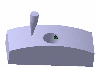
![]()