![]()
This task explains how to generate the trace of a point from a V5 mechanism which can be simulated with laws.
This is very useful in the design process as you can use the resulting trace to design cams.
![]()
Open the Use_Sensors.CATProduct document.
Automatic switch to Design mode:
If you work with the cache system in visualization mode, you no longer
need to use Edit > Representations > Design Mode beforehand as
the switch to design mode is automatic (an eye appears as you point the
product in the geometry or specification tree). All you need to do is click
on the object.
(for more detailed information, refer to DMU Navigator User's Guide-
Viewing the Cache Content)
-
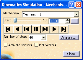
Click Simulation with Laws
 in the DMU Kinematics toolbar
-
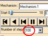
Run the simulation using the simulation buttons
-
Click Close when satisfied.
-
Click Trace
 in the DMU Generic
Animations toolbar.
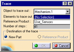
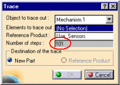
The Trace dialog box appears: -
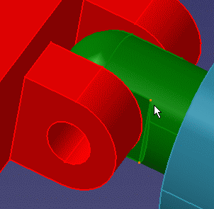
Select a point to trace either in the geometry area or in the specification tree.
-
Select a reference product, click within the field and select Rear_Moving-Arm.1 in the specification tree

-
Click Ok to end the trace creation.

If the Reference product is a not a Part, the trace destination is a New Part document as you cannot only write into a part document.
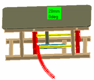
The trace is created and looks like this:
![]()
