V4 Data conversion through Copy / Paste is useful but contains a few restrictions, only V4 geometry is migrated and cannot be edited. In the following example, the Copy As Special process is used; therefore the Specifications are generated in V5.
Clear the option Use of Step-by-step Update and Reroute in Tools > General > Compatibility > V4/V5 SPEC tab.
-
Create a new document in CATIA V5, a new part, Part1. Both documents can be open in the same CATIA window:
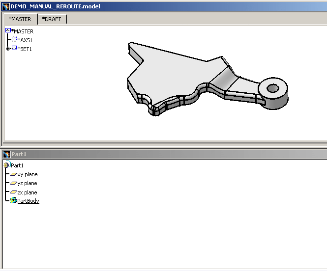
-
Copy / Paste As Special the .model in Part1. A Paste Special dialog box appears, select CATIA_SPEC and click on OK:
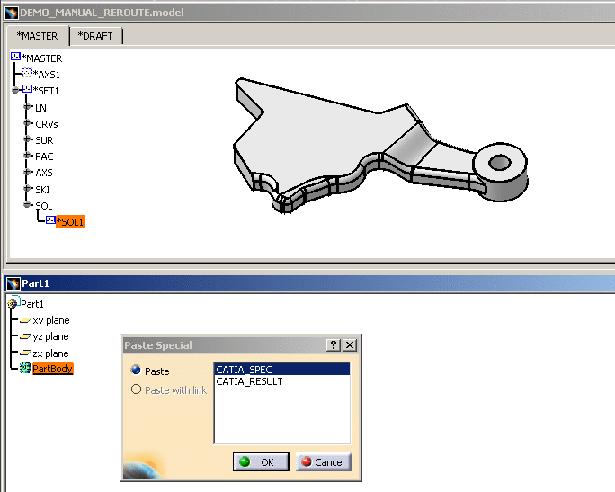
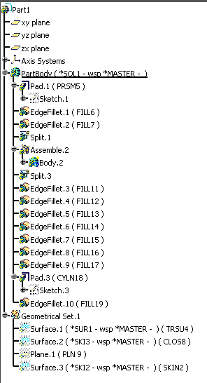
At this step, only specifications or definitions have been built; they are visible in the Specification Tree of Part1. Here is a part of the Specification Tree:
-
Update the document, Part1, so that the geometry calculation operates. When the update is finished, an Update Diagnosis dialog box is displayed:
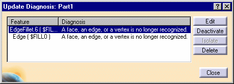
The error is in definition of the Edge.Fillet.6 corresponding to the V4 Fillet ($FILL14) and it cannot be placed into the geometry.
-
Press the button Edit in order to modify the Fillet and the error is explained in a new dialog box entitled Feature Definition Error. Click on OK to delete the Edge.
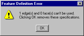
-
Select the object (highlighted with yellow dots) to be filleted in the Edge Fillet Definition dialog box. The radius (R3 in green) and Propagation correspond to the V4 data that have been kept during the transfer.
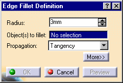
Before you select the Edge:
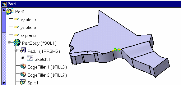
After the selection:
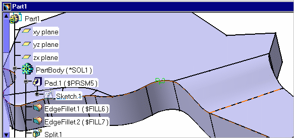
-
Click on OK: the calculation of the fillet geometry is launched. The result in V5 is:
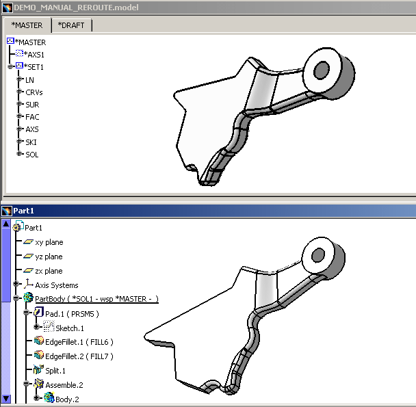
Both objects in V4 and V5 are similar and you can now modify the V5 CATPart in CATIA Version 5. At the same time there is an additional element, Pad.3 ($CYLN18) present in the geometry space.
In this transfer, the V4 geometric curve is migrated into V5 and it is visualized in yellow. This is what we call the reroute mechanism: a contextual primitive (a Fillet, a Chamfer, a Support or a Feature Draft) is unsolved and the Modeler (in Part Design) is able to visualize the former geometric shape and the Fillet's Specifications when they are not solved in V5.
![]()