The general concept is to provide a tool that will allow you to create virtual segments (Segments) of the pelvis, trunk, neck and head on which you will be able to edit preferred angles with a score.
This can be recorded during a simulation and exported for analysis.
To do this, create virtual segments (Segments) by selecting two manikin's segments. This Segment will have a calculated Range of Motion (ROM) based on the ROM of each segment of the pelvis, trunk, neck and head (central segments as we will call them in the rest of this document), included between the two selections. These virtual Segments can be created for any Degree of Freedom (DOF). Then, you will be allowed to specify standard Preferred Angles with a score and, by the same way, analyze the posture using the Postural Score panel.
-
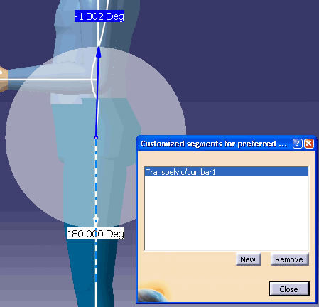
Select the Customized Segment
 from the Angular Limitations toolbar.
 -
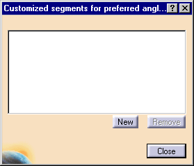
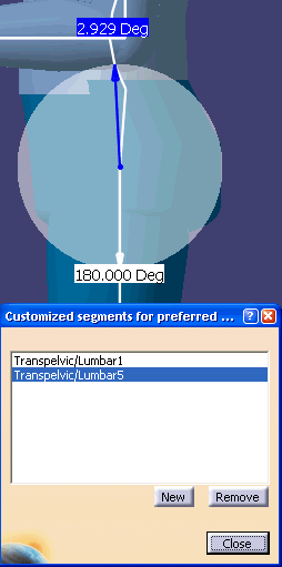
The dialog box appears without any existing customized Segment selected. So, you can either select an existing one that was previously created, or create a new one.
-
To create a new customized Segment, select New.
-
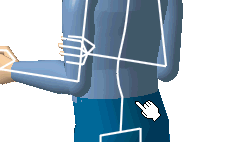
The command prompt asks "please select the first segment to which the Segment will be attached". Select the required segment.
-
The command prompt asks for a second segment, select the required segment.
-
The data appears in the dialog box, and the angle appears on the manikin.
-
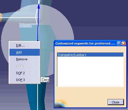
Select the Customized Segment to activate the Segment in the 3D Geometry window.
-
Right-click in the shaded area to access the Contextual window.
-
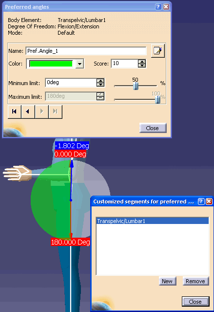
Select Add to create the preferred angles. (Don't forget to put in a score number (1-10)). You will be able to add Preferred Angles by using the current contextual menu command. The following dialog box will also pop-up allowing you to edit the zones. This dialog is exactly the same one that you will find on the standard segments (Segments). The Body Element field will show which segments are the reference of the customized Segment.
-
Add required amount of customized segments by using the Close, and selecting Add again from the contextual window.
-
Close the Customized segments window, and follow the same procedure for a second customized segment.
-
Close the Customized Segments for preferred angles dialog box when completed.
-
To remove a customized segment, select the item in the list. The Remove button will simply remove the Segment item that has been pre-selected in the list.

-
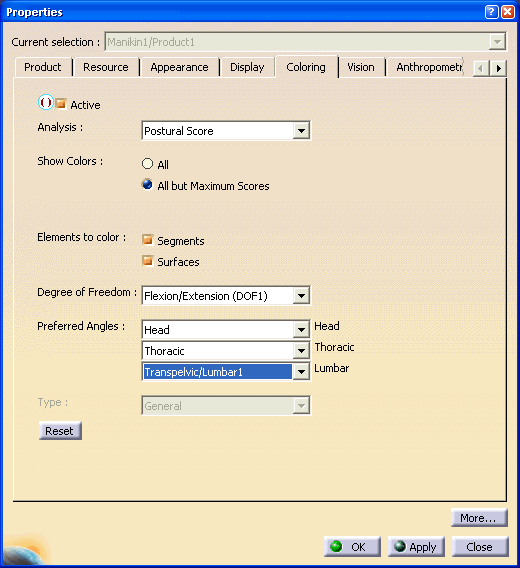
To view the customized Segments on the manikin, right-click on the manikin, in the contextual window, select Properties, Coloring tab. Select the options as shown.
-
Select the Apply, and OK. The manikin's segment color changes to the selected preferred angle.
-
Select the Edits the angular limitations and the Preferred angles
 , and
select the manikin's chest. Right-click on the preferred
angles area, and select the proper DOF if required.
, and
select the manikin's chest. Right-click on the preferred
angles area, and select the proper DOF if required.
-
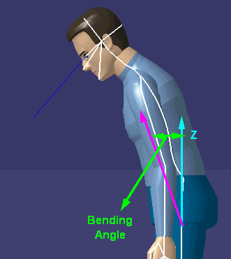
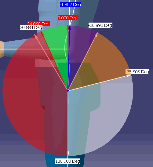
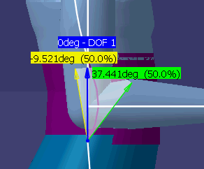
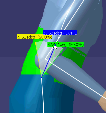
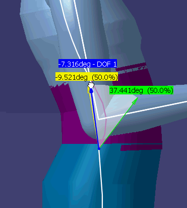
A selection or creation of a Customized Preferred Angle will activate the display of the arrows representing the current position (blue arrow) and the cumulative range of motion (white arrows) in the 3D viewer.
-
The 0 degree position of any customized preferred angle is defined when the body is standing straight (anatomical posture). The Preferred Angles edition and creation capability will be available on this Segment just like on the standard Segments (segments).
-
Click the O deg, (hold and move the mouse), will move the manikin. The color will change according to the preferred angles that was previously set.
-
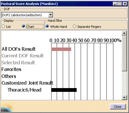
The result of the Customized Preferred Angles will be displayed in the Opens the Postural Score Panel
 just underneath the
Standard Segments in both the list and chart
presentations. To view this DOF, in the DOF pull-down window, select the
DOF2 (abduction/adduction). If you move the manikin the Postural
score shall be reflected in the dialog box.
just underneath the
Standard Segments in both the list and chart
presentations. To view this DOF, in the DOF pull-down window, select the
DOF2 (abduction/adduction). If you move the manikin the Postural
score shall be reflected in the dialog box. 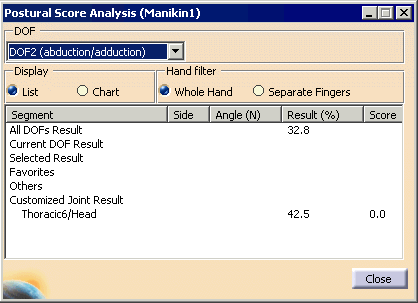
-
The results will be updated and can be exported in a report with the Preferred Angles of the standard Segments.
-
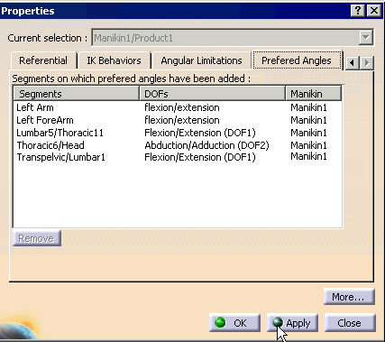
Finally, the Customized Preferred Angles will be listed in the Preferred Angles Properties, tab as well.