Create an envelope sketch and name it EnvelopeProfile. The sketch must have eight vertices on it. This could be a combination, for example, of four lines and four arcs. When you are placing the vertices, start from the top left and continue clockwise.
Use the envelope sketch when a hanger is used with a lofted pathway. The loft assumes the shape of this sketch.
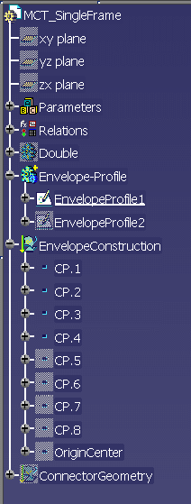
Add four 3-D points to the hanger under EnvelopeConstruction as shown in this specifications tree.
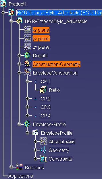
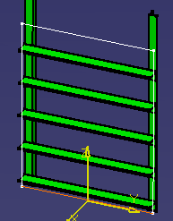
Name the 3-D points CP.1, CP.2, CP.3 and CP.4. Place these points on the corners of the octagonal shape. These points need to lie on the envelope profile.
Name the part body EnvelopeConstruction. The specifications tree shows how these elements appear. Alongside the tree, you can see the EnvelopeProfile with the four 3-D points showing at the corners.
Create a 3-D point at the location that will be the starting point for offset measurement. This measures the length required for the downcomer. Place another 3-D point at the center point of the hanger. This is where a connector will be placed for routing purposes.
Create two envelope sketches for the cable penetration parts, and name them EnvelopeProfile1 and EnvelopeProfile2.
Using these envelope profiles allows you to get a better visualization of the lofts that are created later in the design process.
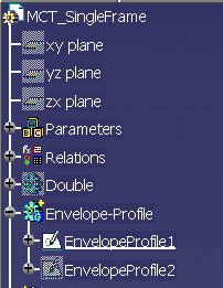
Create one envelope profile at the front of the MCT Part, and one profile at the back. Each profile must be comprised of eight vertices as shown in the following example:
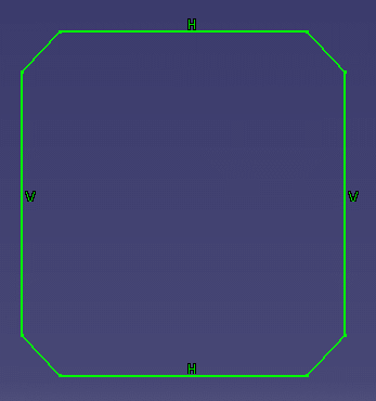
Use this envelope sketch when an MCT is used with a lofted pathway. The loft assumes the shape of the sketch.
Add nine 3-D points to each of the envelope profiles created earlier.
Place them under EnvelopeConstruction (ordered geometrical set). Four 3-D points are for the envelope profiles, one 3-D point is for the origin, OriginCenter.
The others are similarly arranged in a clockwise direction, with the starting point at the top left corner of the profile.
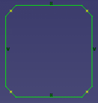
Because the corners in this example have edges, the location of these points at each corner should be at the middle point of the corner segments. Insert the OriginCenter point between the two envelope profiles, equidistant to them.
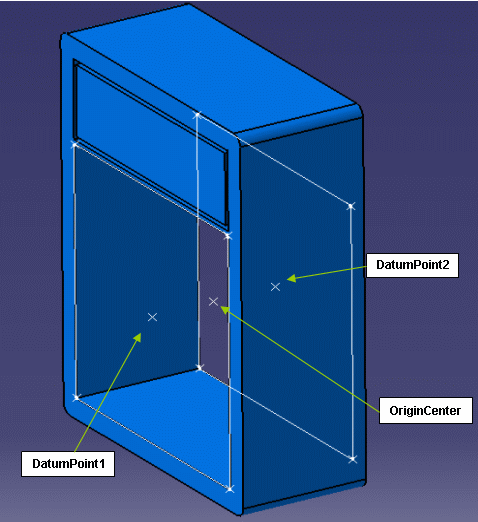
Define one Hanger Attach Connector, two Hanger Part Connectors and Hanger Support Connectors for the cable penetration Part. The number of support connectors depends on the number of frames present in the penetration part.
To build these connectors, you need extra geometrical features (under ConnectorGeometry ordered geometrical set).
For Hanger Part Connectors, define an alignment line that passes through the center of each envelope profile. The face will be the plane on which envelope profile lies. Pick the top face of the part for orientation.
For Hanger Support Connectors, define an alignment line at the center of the inside bottom face of each frame. You can do this by making a plane (under the ConnectorGeometry ordered geometrical set) at the center of the bottom face of each frame. You can do this only for the bottom row frames. The frames on the upper rows use the same plane. You then need to create an alignment line on the respective sketch planes.
This is similar to the Hanger Support Connector that is located on the top-center of the tier. For multiframe penetration parts, the Part will be filled in the order of the Hanger Support Connectors.
![]()