Styling a Fillet

This task explains how to create an ACA fillet surface between two given surfaces.
Open the StylingFillet.CATPart document
  1. Click the Styling Fillet icon:


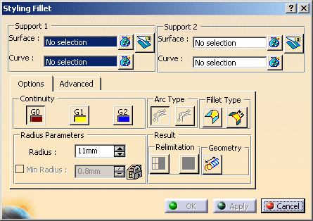
The Styling Fillet dialog box is displayed. Following dialog box is open in Options mode.


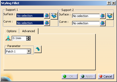
The following dialog box is open in Advanced mode.

  1. Select the two surfaces where you want to create the fillet.


Two vectors and the continuity symbol appears (G2).
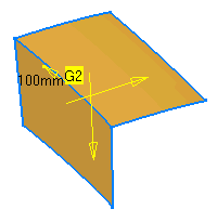
 
  1. Click Apply create the fillet. This option is only available for G2 and not for G0 or G1.
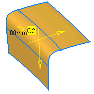


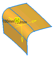
When you activate minimum radius, a new vector appears enabling you to change the minimum radius in the middle of the fillet. Alternatively, you can change the value using the up and down arrows in the Minimum Radius.
 

The Styling Fillet dialog box displays several options helping you to create the fillet:

  • Continuity: You can specify the order of continuity between fillet and reference surfaces (G0, G1, and G2). In case of G0 continuity, it is not relevant to call this option a G0 fillet , but it is useful in some cases to be able to access this functionality without changing command.

  • Radius: Fillet radius.

  • Radius Parameters

    • Minimum Radius: Minimum radius in the middle of the fillet (optional). You can provide the minimum radius in the middle of the fillet (optional). This option is available only for G2 continuity mode and is not compatible with True Minimum option.

    • Variable Radius: This option activates the variable radius (only possible if edge tolerance is met). A UI-Tool (vector) appears at each end of the fillet surface with which you can modify the radius at each end individually. Additional manipulators can be created with these manipulators at two ends. The newly created manipulators cannot be used for creation of new manipulators. You can only change the position of these new manipulators.

  • Fillet Type:

    • Variable: Activates variable radius (only possible if edge tolerance is met).

    • Chordal Fillet: (only for Variable off) Instead of the radius, the chord length of the cross-sections defines the fillet.

    • Trim Input: Trims the reference input surfaces on fillet boundaries:

      • This trimming method is exact and is it no approximation.

      • If the trim input option of the fillet is checked, then inputs for the fillet are put in no show mode. And when the trim input option is unchecked, the inputs for the fillet operation are put in show mode.

  • Arc Type: This option influences the fillet surface only in fillet direction and available only for G1 continuity mode. Providing this option creates a fillet with specific order and segmentation as follows:

    • Blend: Order – 4 and Segment 1

    • Approx : Order – 6 and Segment 1 (Creates a circular Bezier Approximation)

      Arc type Approx means that the arc of circle is a polynomial with only one segment and within tolerance to the exact arc of circle. In this case, the resulting surface is a polynomial surface. If you has required a mono patch approximation it is a Bezier surface (polynomial surface with one segment in both direction U and V). In all cases with “approx” option the resulting surface is not a simulated Bezier mesh.

    • Exact: Order – 3 and Segment 1 (Creates a rational surface with true circular sections)

      Arc type Exact means that the arc of circle is an exact representation with a rational BSpline curve.  Consequently, the created surface is a polynomial surface with “approx” option and it is a rational BSpline surface with “exact” option.

  • Independent Approximation: Independent internal approximation. The parameterization of one fillet surface is calculated disregarding the parameterization of the neighboring fillet surfaces. The interest of this option is the approximations are independent face by face, so a “bad” Control Points mesh on a face could not influence the other faces if this option is enabled.

  • Parameter: Different options for parameterization of the result and fillet surface.

    • Default: Internal computed best filling parameterization.

    • Patch 1: Parameterization is taken from the 1st patch. For Advanced mode, one Patch 1 is available.

    • Patch 2: Parameterization is taken from the 2nd patch.

    • Average: Average of parameterization from patch 1 and patch 2 is taken.

    • Blend: Traces have parameterization of their correspondent surface.

    • Chordal: The parameterization is the chordal parameterization.

  • Edge Tolerance: Tolerance for common edge detection. If no common edge is detected, variable fillet is not possible.

  • Relimitation: The Relimitation options are active only when the Extrapolate is ON.

    • Trim Face:Face trimming of reference surfaces on fillet boundaries. The basic surface stays untouched. This is like: Command break, with the option Geometric : OFF.

    • Trim Approx:The basic surface changes. The result is not a face. This is like: Command break, with the option Geometric: ON. The result TRIM APPROX geometrically trims the Fillet surface (i.e., produces no face). This form of trimming is generated using an approximation and is therefore never mathematically exact.

  • Extrapolate: Fillet surface also on extrapolation of reference surfaces.


The Dashboard options that you can use are as follows:

  • Create Datum : This option is to create a datum feature.

  • Insert In A New Geometrical Set : This option is to create the resultant disassembled bodies into a new ordered geometrical set.

  • Temporary Analysis : This option allows launching of any analysis command without exiting the current command, and evaluates the result of various analysis commands in a temporary mode.

  • Furtive Display : This option from the dashboard is used to display control points of the created elements.


Modifications and Trim Input: With the use of trim input option in each support set you can get different result as follows:

Serial Number Trim Input (Support 1) Trim Input (Support 2) Result
1 Uncheck Uncheck Only Surface Set 1 will be trimmed.
2 Check Check Only Surface Set 2 will be trimmed.
3 Uncheck Check Both Surface Set 1 and Surafce Set 2 will be trimmed.
4 Check Check Nothing will be trimmed.

If the none of trim input options is checked, the fillet is created as a creation feature. If atleast one of the trim input options is checked, the fillet feature created as a modification feature. At the time of creation of the feature, you can specify the trim input option and change it as well.  Hence it is possible for you to decide whether to create Creation feature or Modification feature at the time of creation. However, once the feature is created, you cannot change the trim input options, that is, type of feature - creation or modification, can not be changed. This means that while editing the feature the trim input options will not be available.

Also the Keep Original option in the dashboard is inactive in the edit mode.

F8 and Ctrl keys: An element can be added by simply clicking the F8 key. Multiple elements can be added by keeping Ctrl key pressed and selecting elements. Clicking on an element (without pressing Ctrl key) when multiple elements are selected will result in selection of that element and removal of other elements from the list. You can also remove or replace an element of the current selection list using the push buttons. You can change from one selection state to other by using the F8 key.

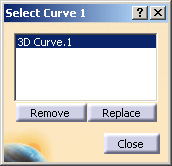
Multi-selection bag: Click on the Multi-selection bag icon and select the curve or surface. The Select Curve (n) dialog box appears, where n is the number of the dialog box opened. You can select one or more elements and choose to Remove or Replace them by using the Remove or Replace options respectively.

Input changes through 3D: In the 3D UI, continuity and radius (constant radius in normal mode and variable radius in variable radius mode) are displayed. These can be edited in the 3D as well as through the dialog box. Two arrows are also displayed to select the quadrant of the fillet to be created.

The radius (constant radius, minimum radius, variable radius) and simplification parameter (small surface tolerance) values can be inserted in the specification tree and you can edit them and modify the fillet feature directly.

Parameter in the Specification Tree: In the specification tree, you can change the radius and minimum radius under the fillet.

Quadrant selection for fillet: You have to select the appropriate direction to make the fillet.

Error handling: If incorrect options are chosen no fillet can be created and the following error message will appear.