-
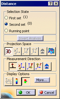
Click the Distance Analysis icon:

| The Distance dialog box is displayed. The fitted surface is
already selected from the previous task. |
 |
-
Select the Normal distance direction

-
Select the Limited Color Range mode

-
Click the More>> button to display further
option.
-
Select the Color scale option to display the
color range.
-
Select the Min/Max values option to display
these values on the geometry.
-
Select the Points option.
-
Unselect the Spikes option.
-
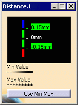
From the displayed color range, set the colors to:
-
blue for all points located over 0.15mm above
the surface
-
green for all points between 0.15 and -0.15mm
away from the surface
-
red for all points located beyond
-0.15mm below the surface
|
 |
-
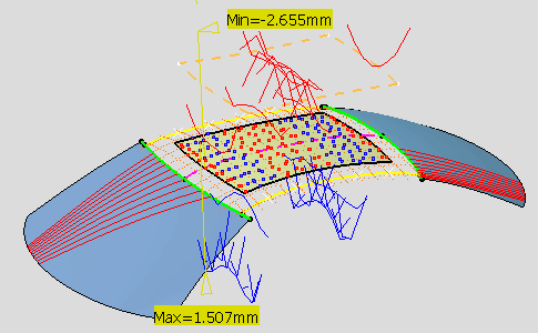
Select the cloud of points.
| Points are dynamically displayed and the minimum and maximum deviations
are identified on the surface. |
 |
-
Click OK.
| The parts of the surface that lie above the cloud are identified by blue
dots, and red for parts lying below the cloud. This means that the
surface needs to be smoothed further, so that all points turn green
indicating a perfect matching with the cloud of points. |
-
From the specification tree, choose the Show/Hide
contextual menu on the distance analysis to hide it for the moment.
-
From the specification tree, double-click the Reflect Line Analysis.1.
| The Reflection Lines dialog box is displayed and a grid of
neons appears in the geometry. |
-
Click the front and rear windshields to remove the
current reflect lines, then select the roof patch to apply the reflect
line analysis and move the neons.
-
Choose the Top View icon
 from the View toolbar.
-
Set the neons parameters to N=20 (number of neons in
grid) and D=200mm (distance between two neons).
-
Zoom in till you locate the green dot symbolizing the
analysis eye.
-
Right-click on this eye and choose the Edit
contextual menu.
| The Tuner dialog box is displayed. |
-
Type in the eye's coordinates: 1850mm, 0mm, 3000mm.
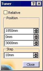 |
| This moves the eye directly above the roof patch. |
-
Click Close in the Tuner dialog
box, then OK in the Reflection Lines dialog box.
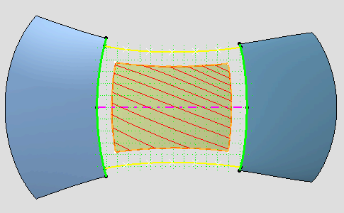
| The analysis is visible on the roof patch: |
 |
![]()