Open the Groove.CATPart document, and recognize the groove as described in the task.
-
Click the Manual Feature Recognition icon
 .
.
The Feature Recognition dialog box that appears displays a list of features you can recognize.Using this product release, the features you can recognize are the following ones:
- Pad
- Hole
- Fillet
- Chamfer
- Shaft
- Groove
- Boolean
- Draft
-
Check the Pocket option.
-
Select the face as shown.
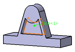
To recognize pockets (or pads), the application does not let you select several faces. You can notice that the Chain Faces option is grayed out.
-
Click OK to confirm and close the dialog box. A pocket feature has been recognized. Pocket.1 has been added to the specification tree, meaning that it is now possible to edit this feature.
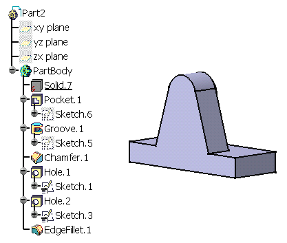
![]()
More About Recognizing Pockets or Pads
Several Possible Solutions
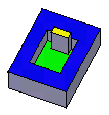
Open the Pocket.CATPart document.
-
Click the Manual Feature Recognition icon
 to display the Feature Recognition dialog box.
 -
Select the green face as the bottom face of the pocket.
-
Click the Recognize Up to face field and select the yellow face as the top face for the pocket.

-
Click OK to confirm and close the dialog box.
A pocket feature has been recognized. The "Pocket.1" entity has been added to the specification tree, meaning that it is now possible to edit this feature. If you do not specify the limiting face you want, the application uses the face that is nearer to the bottom face as the top face. In our example, it would be the blue face.
Recognizing Pockets or Pads by Selecting Edges
Instead of selecting faces, you can select edges to recognize pockets or pads. This method lets you recognize a smaller region. To perform this scenario, use Solid2 in the Pocket.CATPart document.
-
Click the Manual Feature Recognition icon
 to display the Feature Recognition dialog box and check the
Pocket option.
 -
Select the bottom face as the bottom face of the pocket.
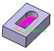
If you recognize the pocket, the simplified solid looks like this:
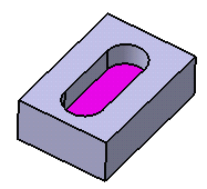
In this case, the profile includes four elements only: two lines and two circular arcs.
-
Now, instead of selecting the bottom face, replay the scenario and select the edge as shown:
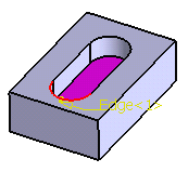
-
After recognizing the pocket, the simplified solid looks like this:
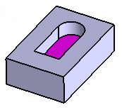
In this case, the profile includes only one element, that is a circular arc.