Perform the previous task using the Tasks.CATPart document.
-
Click the Manual Feature Recognition icon
 .
.
The Feature Recognition dialog box that appears displays a list of features you can recognize. Using this product release, the features you can recognize are the following ones:- Pad
- Hole
- Fillet
- Chamfer
- Shaft
- Groove
- Boolean
- Draft
-
Check the Hole option.
-
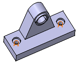
Select both faces as shown.

-
As the Chain Faces option is activated, the application includes propagated faces in the selection. This is why the Selected Objects field shows a list of ten faces. All selected faces are highlighted in the geometry area too.
-
Click OK to confirm and close the dialog box.
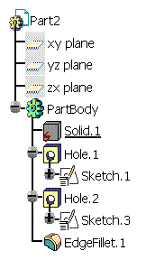
Two hole features have been recognized. Hole.1 and Hole.2 have been added to the specification tree, meaning that it is now possible to edit these features.
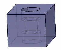
Recognizing Complex Holes

- as 3 simple holes
- as 1 counterbored hole and 1 simple hole
For more information about the different types of holes, refer to Creating Holes, from the Part Design User's Guide.