This task shows
you how to create a 1D mesh part by extracting edge elements of an existing
2D mesh part.
You will then generate 1D elements (bar or beam).
For more details about the bar and beam elements, refer to the Finite
Element Reference Guide.
You can extract 1D elements from Surface Mesh part, Advanced Surface Mesh part, Octree Triangle Mesh part, Coating 2D Mesh part or any 2D transformed mesh part.
- This functionality is only available with the FEM Surface (FMS) product.
- The 2D mesh parts must be updated.
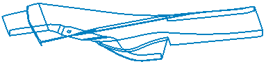
Open the Sample06.CATAnalysis document from the sample directory.
-
Update the 2D mesh parts.
To do this, right-click Nodes and Elements and select Update All Meshes.
-
Click Coating 1D Mesh
 in the Mesh Transformations toolbar.
The Coating 1D Mesh dialog box appears.
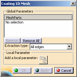
- Global Parameters:
- Mesh Parts: lets you select the 2D mesh parts from
which you will create the 1D mesh part.

- Multi-selection of 2D mesh parts is available.
You can select Surface Mesh part, Advanced Surface Mesh part, Octree Triangle Mesh part or Coating 2D Mesh part or any 2D transformed mesh part. - The 2D mesh parts must be updated.
To do this, right-click Nodes and Elements and select Update All Meshes.
- Multi-selection of 2D mesh parts is available.
- Remove: lets you remove a selected mesh part.
- Remove All: lets you remove all the selected mesh parts.
- Extraction type: lets you specify the edge element
you want to extract to create a 1D mesh part.
- All edges: each edge of the surface mesh parts will generate a bar or beam element.
- Boundary edges: each boundary edge of the surface mesh parts will generate a bar or beam element.
- Internal edges: each internal edge of the surface mesh parts will generate a bar or beam element.
- Constrained edges: each constrained edge of the surface mesh parts will generate a bar or beam element.
- Non constrained edges: each non constrained edge of the surface mesh parts will generate a bar or beam element.
- None: only the local specifications will be used to generate 1D elements.
- Correspondence between surface elements and extracted 1D
elements:
Solid elements
Extracted elements
TR3 BAR
TR6 BAR3
QD4
BAR QD8 BAR3
- Mesh Parts: lets you select the 2D mesh parts from
which you will create the 1D mesh part.
- Local Parameter:
- Add a local parameter
 :
lets you include or exclude elements.
:
lets you include or exclude elements.
This button is available as soon as you select a 2D mesh part.
- Add a local parameter
This button lets you display the Coating 1D Specification dialog box.
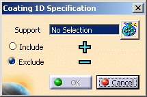
- Support: lets you select one or several edges you
want to add or remove locally from the set of edge elements you
want to extract. You can also select groups created under a
mesh part.
-
You can only select 1D geometries or 1D groups as local specification supports.
This support must have the same dimension as the elements you want to extract. -
Multi-selection of supports is available.
To do this, select in sequence the edges or groups you want to ignore or constrain. -
You can only select groups that belong to the mesh parts you have selected in the Global Parameters.
- Include: lets you select one or several edges (or groups of edges) you want to add to the set of edges you will extract.
- Exclude: lets you select one or several edges (or groups of edges) you want to remove from the set of edges you will extract.
-
- Global Parameters:
-
Select one or several 2D mesh parts.
In this particular example, select the Advanced Surface Mesh.1 mesh part.
-
Select Constrained edges as Extraction type option.
-
Click Apply.
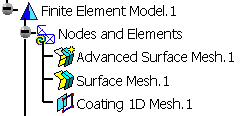
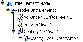
The Coating 1D Mesh.1 feature now appears in the specification tree.
The extracted edges are displayed on the geometry.

For a better visualization, hide the existing mesh parts and the geometry using the Hide/Show contextual menu.
-
Click the Add/Remove Mesh
button. -
Select edges directly on geometry.
If needed, show the geometry using the Hide/Show contextual menu.
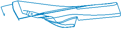
In this particular example, select two edges as shown below :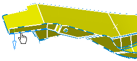
and then
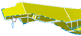
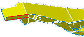
As soon the edges are selected, they are red-highlighted.
-
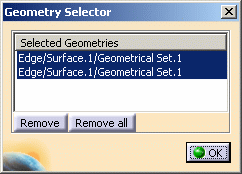
Click the Geometry Selector
 button to
visualize the edges you selected.
button to
visualize the edges you selected.The Geometry Selector dialog box appears.
-
Click OK in the Geometry Selector dialog box.
-
Click Exclude in the Coating 1D Specification dialog box.
-
Click OK in the Coating 1D Specification dialog box.
-
Click Apply and then OK in the Coating 1D Mesh dialog box.
The Coating Local Specification.1 feature now appears in the specification tree under the Coating 1D Mesh.1 mesh part..
The 1D mesh part is displayed on the geometry. For a better visualization, hide the geometry.