This task shows you how to identify duplicate nodes in a
single mesh or an assembly of meshes.
Duplicate nodes are nodes that are coincident or very close.
The duplicate nodes are red-highlighted and the elements linked to a duplicate node are highlighted in light blue.
Open the Sample16.CATAnalysis document from the samples directory.
This example contains two solid mesh parts and one of the Surface Mesh.2
mesh part is built with mesh capture.
For a better visualization, you can hide the geometry using the
Hide/Show contextual menu.
-
Click Duplicate Nodes
 in the Mesh Analysis Tools toolbar.
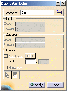
The Duplicate Nodes dialog box appears.
-
Clearance: lets you define the clearance from which you decide that a node is considered as duplicate. In other words, the clearance value lets you define the coincidence condition.

The clearance maximum value must be lower than the minimum edge length.
If it is not the case, a warning message appears:-
Click Yes to change the Clearance value.
-
Click No to postpone the Duplicate Nodes command.
-
-
Nodes: gives you the number of duplicate nodes.
-
Global: gives you the total number of duplicate nodes (hidden and shown duplicate nodes).
-
Shown: gives you the number of duplicate nodes that are shown (if a duplicate node belongs to a hidden mesh part, this node is not taken into account).
-
-
Subsets: gives you the number of subsets containing duplicated nodes.
-
Global: gives you the total number of subsets (hidden and shown sets).
-
Shown: gives you the number of subsets that are shown (if a set is hidden, this subset is not taken into account).
-
-
Browse: lets you auto-focus and show information on the visible duplicate subsets.
-
Auto focus: lets you localize easily visible duplicate nodes by focus on them.
-
Current: gives you the number of detected duplicate nodes and lets you visualize a particular duplicate node either by entering a number or by clicking the browse buttons.
-
Show information: lets you display information about visible duplicate subsets.
-
-
Select duplicate entity
 : lets
you display information about a duplicate node.
If you click this button, the Duplicate Node dialog box appears.
This button is available only if at least one duplicate node has been found.
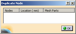
- Nodes: gives you the identifiers of the selected node.
- Location: gives you the node coordinates.
- Mesh Parts: gives you the name of linked mesh part.
Then you have to select a duplicate node to fill this dialog box.
-
Generate Report
 :
lets you export duplicated node data including centroid and mesh
part names in a .html file.
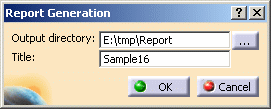
If you click this button, the Report Generation dialog box appears.
This button is available only if at least one duplicate node has been found.
-
Output directory: lets specify the directory in which the report file will be stored.
-
Title: lets you modify the name of the report file.
-
-
-
Enter a Clearance value.
In this particular example, enter 0mm as Clearance value.
-
Click Apply.
The Duplicate Nodes dialog box is updated:
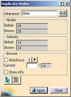
The duplicate nodes are red-highlighted and the linked elements are highlighted in light blue:
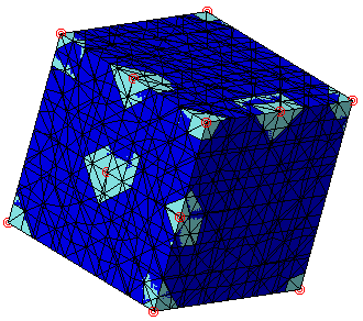
You can hide one of the solid mesh part for a better visualization.
In the following example, the Tetrahedron Filler Mesh.1 mesh part is hidden: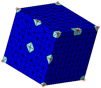
-
Click Select duplicate nodes
 .
. -
Select a duplicate node.
The Duplicate Node dialog box is automatically updated with the following information:

-
Click OK.
-
Click Generate Report
 .
. -
Choose the directory and the title of the report file.
-
Click OK.
The .html report is automatically displayed:
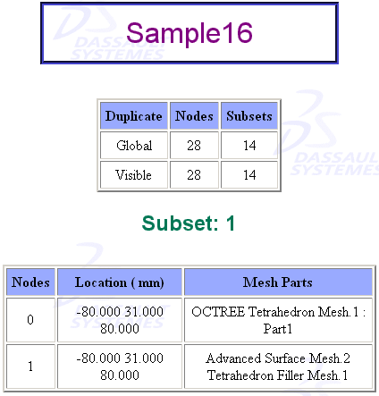
-
Click Close in the Duplicate Nodes dialog box.
![]()