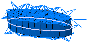
This task shows how to mesh surface welding connections (also called adhesive surface connections).
You can mesh the Surface Analysis Connection and Surface Analysis Connection within one Part created in the Generative Structural Analysis workbench. These two connections can only be created if you installed the Generative Structural Analysis (GAS) product.
|
Connections |
Support |
|
Analysis Connections |
One or two |
For more details about analysis connections, refer to the Generative Structural Analysis User's Guide - Analysis Connections.
Open the Sample13.CATAnalysis document from the samples directory.
-
Click Surface Welding Connection Mesh
 in the Welding Meshing Methods toolbar.
The Surface Welding Connection Mesh dialog box appears.
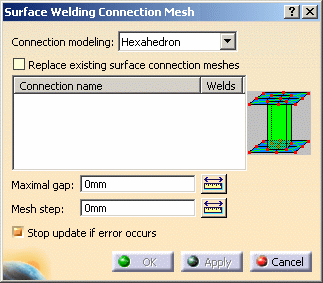
- Connection modeling:
Connection modeling
Non compatible mesh (default behavior)
- Hexahedron

- Replace existing weld connection meshes: allows you
to select a weld spot connection that has been already associated
to a mesh part.

You must activate this option before selecting the surface analysis connection.
If not, a warning message informs you that the surface analysis connection has been already meshed. - Maximal gap: lets you specify the distance between
the surface and the furthest support to weld.

- The value must be strictly positive.
- While the Maximal gap value is null, the OK and the Apply buttons will be not available.
- Mesh step: lets you specify the mesh size of the surface.
- Stop update if error occurs: lets you stop the
Update all meshes process.
If this option is activated and if you use the Update all meshes contextual menu, only the meshes created before the surface welding connection mesh will be updated.
- Connection modeling:
-
Select the connection you want to mesh in the specification tree.
In this particular example, select the Surface Analysis Connection.1 object in the specification tree (under the Analysis Connections Manager.1 set).

The Surface Welding Connection Mesh dialog box is updated.
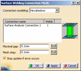
-
Set the desired parameters.
In this particular example:
-
Select Hexahedron as Connection modeling option.
-
Enter 5mm as Maximal gap value.
-
Enter 2mm as Mesh step value.
-
Select the Stop update if error occurs check box.
-
-
Click Apply and then OK.
The specification tree is updated and a Surface Welding Connection Mesh.1 appears:
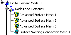
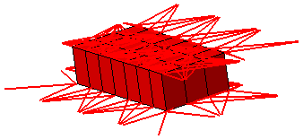
The connection mesh part is displayed: in this particular example, the color of the connection mesh part has been changed using the Color Mesh contextual menu (for more details, refer to Coloring Mesh Parts).
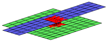

For a better visualization, you can hide the Advanced Surface Mesh.1, Advanced Surface Mesh.2 and Advanced Surface Mesh.3 using the Hide/Show contextual menu:
-
Click Surface Welding Connection Mesh
 in the Welding Meshing Methods toolbar.
 -
Set the desired parameters.
In this particular example:
-
Select the Surface Analysis Connection within one Part.1 as Connection name.
-
Select Hexahedron as Connection modeling option.
-
Enter 4mm as Maximal gap value.
-
Enter 2mm as Mesh step value.
-
Select the Stop update if error occurs check box.
-
-
Click Apply and then OK.
The specification tree is updated and a Surface Welding Connection Mesh.2 appears:
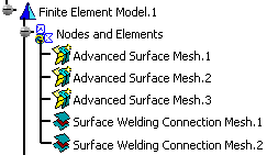
The connection mesh part is displayed: in this particular example, the color of the connection mesh part has been changed using the Color Mesh contextual menu (for more details, refer to Coloring Mesh Parts).


For a better visualization, you can hide the Advanced Surface Mesh.1, Advanced Surface Mesh.2 and Advanced Surface Mesh.3 using the Hide/Show contextual menu:
