This task will show you how to define constraints on edge
nodes distributions.
To do this, you can select edges, vertices (on the geometrical
simplification), curves or points (using the geometry).
You are still in the Advanced Surface Mesher workshop.
-
Click Add/Remove Constraints
 in the Local Specifications toolbar.
Both the Add/Remove Constraints dialog box and the Trap Type dialog box appear.
-
Select the edge to be constrained.
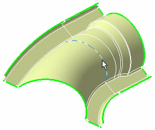
This edge is now yellow colored and the Add/Remove Constraints dialog box is updated.
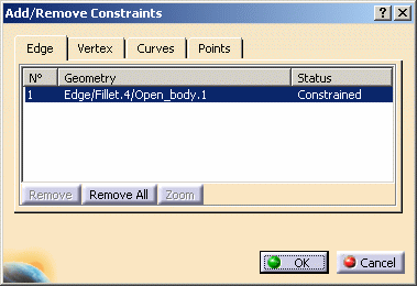
-
Click OK.
-
Click Imposed Elements
 in the Local Specifications toolbar.
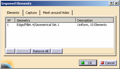
The Imposed Elements dialog box appears.
-
Select the edge you have just constrained.
The Edit Elements Distribution dialog box appears.
-
Define the parameters of the new distribution.
In this particular case:
- Select the Uniform distribution type.
- Enter 10 as Number of elements.
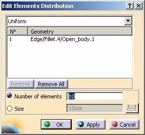
-
Click OK in the Edit Elements Distribution dialog box.
The nodes (or elements) are distributed on the selected edge.
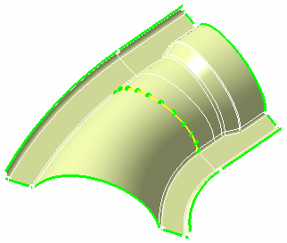
The node distribution description now appears in the Imposed Elements dialog box.
-
Click OK in the Imposed Elements dialog box.
At this stage, distributions are stored in the mesh definition.
You can now launch the mesh operation.