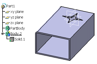
-
Right-click Body.1 and select the Copy contextual command.
The PartBody contains the geometry of Solid Functional Set.1.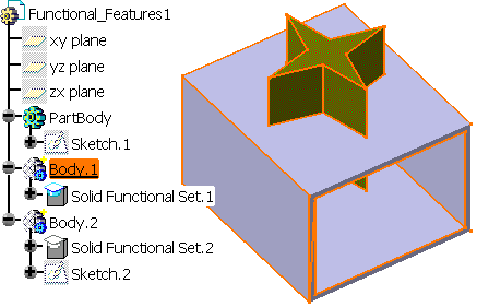
-
Open a new CATPart document and position the cursor anywhere in the specification tree.
-
Select Edit -> Paste Special....
The Paste Special dialog box that appears proposes three paste options: -
For our scenario, select the As Result With Link option if not already selected.
-
Click OK to confirm.
Solid Functional Set.1 is copied into the new document. You will notice that the specification tree displays it under the name of Solid.1. A cube represents this solid.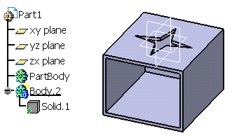
-
Return into the first document to edit the original geometry. For example, enlarge Sketch.1 which supports the shellable feature.
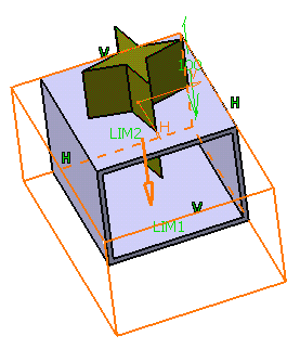
-
Then, use the Part Design Edge Fillet
 command to fillet the lateral edge as shown:
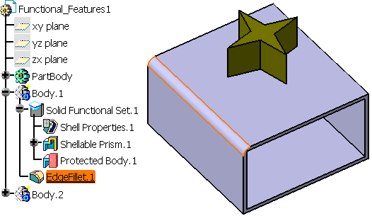
-
Take a look at the new document: the cube graphic symbol used for Solid.1 in the tree now contains a red cross. This means that the initial PartBody underwent transformations.
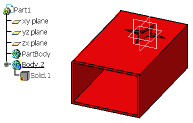
-
To integrate the changes, you need to use the Synchronize contextual command. To do so, right-click Solid.1 object and apply the command.
You can observe that the copy reflects the change: the shellable feature is enlarged and the new edge fillet is added.
