-
Right-click the Datum scheme capture and select Unset Current form the contextual menu, right-click the Hole positioning capture and select Set Current form the contextual menu.

-
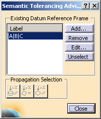
Select the datum reference frame in the Semantic Tolerancing Advisor dialog box.
-
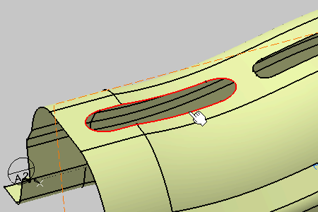
Select the whole hole edges as shown on the part.
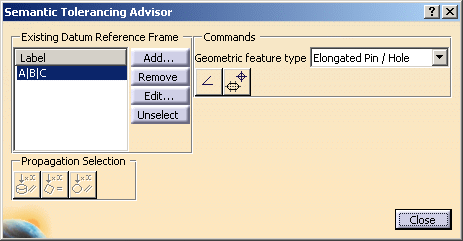
The Semantic Tolerancing Advisor dialog box is updated. Note the geometric feature type: Elongated Pin/Hole. 
-
Click the Position with DRF Specification icon:

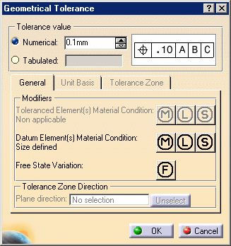
The Geometrical Tolerance dialog box appears. Keep options as is. -
Click the OK in the dialog box.
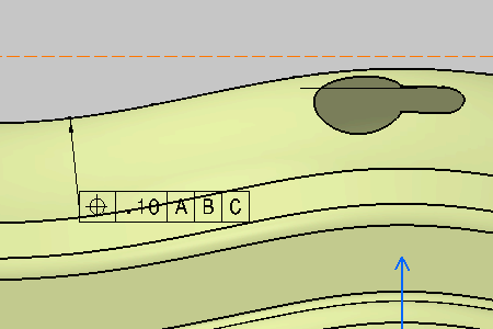
The geometrical tolerances is created. 
The geometrical tolerances is created in the specification tree. -
Select the datum reference frame in the Semantic Tolerancing Advisor dialog box.

-
Select the whole hole edges as shown on the part.
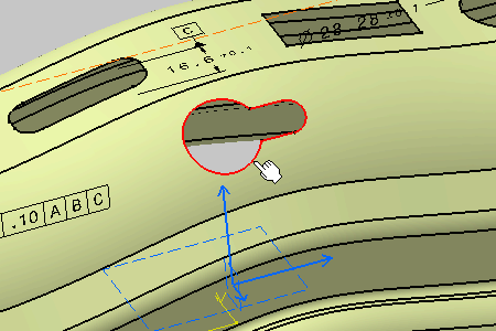
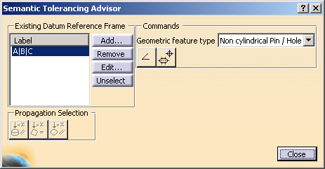
The Semantic Tolerancing Advisor dialog box is updated. Note the geometric feature type: Non cylindrical Pin/Hole. -
Click the Position with DRF Specification icon:

The Geometrical Tolerance dialog box appears. Keep options as is.
-
Click the OK in the dialog box.
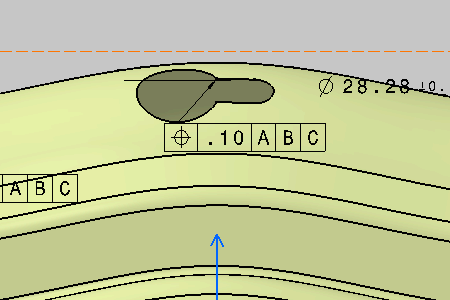
The geometrical tolerance is created. 
The geometrical tolerance is created in the specification tree. -
Do not close the Semantic Tolerancing Advisor dialog box to perform the next task.