This functionality allows you to:
- Create a manual constructed geometry. See also Creating an Automatic Constructed Geometry.
- Associate/disassociate an existing geometry as constructed geometry (or representing geometry) of a tolerancing feature (User surface and Group of surfaces) with another existing geometry as represented geometry.
- You can associate an existing constructed geometry (or representing geometry) with another existing geometry. In this case, the constructed geometry previous association is removed, and then associated with the new selection.
- An existing geometry cannot be its constructed geometry (or representing geometry) and represented geometry at the same time.
- Query the direct or inherited constructed geometry of a given tolerancing feature.
- Remove existing constructed geometry, but not its indirect representing geometries.
- One or several representing geometries may be referenced by a represented geometry, but a representing geometry element can be referenced by only one represented geometry.
- A 3D annotation: the corresponding tolerancing feature is retrieved.
- A geometrical element: the corresponding tolerancing feature is retrieved or created.
-
Select the datum.
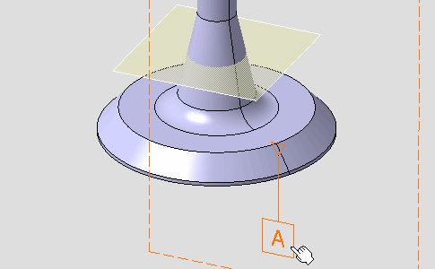
The Constructed Geometry Management dialog box appears. 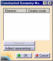
-
Select the reference plane as shown to define the gage plane of the related surface of the annotation.
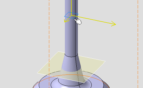
The Constructed Geometry Management dialog box is updated, the constructed geometry is created in manual mode: the associativity is managed by the user. 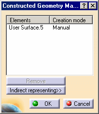
-
Click OK in the dialog box.
-
Click Constructed Geometry Management
 .
.
-
Re-select the previous datum.

-
Click Indirect representing in the dialog box.
The Constructed Geometry Management dialog box displays the indirect representing of the previously created constructed geometry (Plane.1 is a representing geometry element, named User Surface.6, of the selected reference plane in step 3). 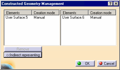
-
Click OK in the dialog box.