- Simulate a signal,
- Display the signal route when the signal is selected.
Simulating a Signal Route
-
Click Routing Simulation
 .
.
You are prompted to select a signal or a segment. -
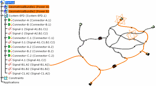
Select the Signal-3.1 functional signal.
The extremities are highlighted and the route is computed.A message informs you of the routing result. The route is highlighted. 
-
Click OK to end the simulation.
Simulating the Signal Route according to Bundle Segment Selection
-
Click Routing Simulation
 .
.
You are prompted to select a signal or a segment. -
Select a segment.
A network is generated along which virtual signals will be routed.
You are prompted to select a segment or a connector.
You need to select at least another two elements to simulate the route. -
Select the first element: a segment or a connector.
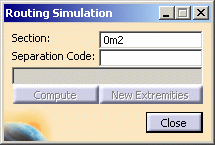
The Routing Simulation dialog box opens. 
The Section and Separation Code fields allow you to define selection criteria.
This information is optional. The compatibility table contains the separation codes of the wires and is customizable in the settings. -
Select other segments and/or connectors forming the ends of the signal route.
The Compute button is enabled. -
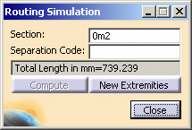
Click Compute to simulate the route and compute the total wire length.
The route is highlighted in the geometry area and the total wire length indicated in the dialog box.
Note: You can copy-paste the total wire length from the dialog box into another application.
-
Click New Extremities to create a new virtual signal.
You are prompted to select other segments or connectors. -
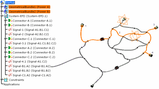
With these four elements selected for example, click Compute again.
The new route is highlighted.
-
Click Close to end the simulation.