This task shows how to create a Smooth Virtual Part between a point and a geometry support.
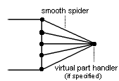
A Smooth Virtual Part is a rigid body connecting a specified point to specified part geometries, behaving as a mass-less rigid object which will softly transmit actions (masses, restraints and loads) applied at the handle point, without stiffening the deformable body or bodies to which it is attached.
The Smooth Virtual Part does approximately take into account the elastic deformability of the parts to which it is attached.
The program proceeds as follows:
-
a node is created in coincidence with the specified handle point.
-
all nodes of the specified geometry supports meshes are connected by a kinematical spider element to the handle node.
-
a set of mean (constr-n) relations is generated between the handle node degree of freedom and the connected nodes degree of freedom.
The Smooth Virtual Part is built with a Smooth Spider element.
To know more about this element, see Smooth Spider in the Finite Element Reference Guide.
Smooth Virtual Parts can be applied to the following types of supports:
|
Geometrical Feature |
Mechanical Feature |
Analysis Feature |
||||
|
Spatial Groups |
Geometrical Groups |
Groups by Neighborhood |
Groups by Boundary |
Others |
||
|
Edge |
|
|
|
|
|
|
Open the
sample28.CATAnalysis document from the samples directory.
A Part Design point was created in the pointed .CATPart
document.
-
Go to View > Render Style > Customize View and make sure the Shading, Outlines and Materials options are active in the Custom View Modes dialog box.
-
Click Smooth Virtual Part
 in the Virtual Parts toolbar.
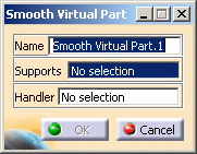
The Smooth Virtual Part dialog box appears.
-
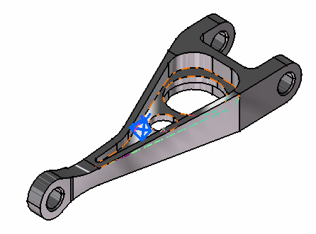
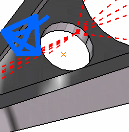
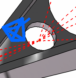
Select an edge or a face of the part as geometry support. In this case, select a face.
-
Position the cursor on the Handler field in the Smooth Virtual Part dialog box and select a point or a vertex as the handler point (the handler point symbol appears as your cursor passes over it). In this case, select a point.
The Rigid Virtual Part dialog box is updated.
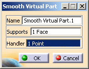
If you do not specifically select a point, the centroid (the point at which the lines meet) will be used as the handler point.
-
Click OK.
When several virtual parts share a same handler point, only one finite element node is generated.
The symbol appearing at the handler point represents the Smooth Virtual Part.
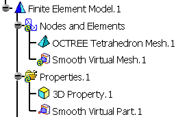
Both Smooth Virtual Mesh.1 and Smooth Virtual Part.1 appear in the specification tree.
- You can select several geometry supports.
- The Smooth Virtual Part will connect all supports to the handle point and softly transmit all actions as a rigid body.
![]()