This task shows how to create a Fastened Spring Connection between two parts.
Only available with the Generative Assembly Structural Analysis (GAS) product.
A Fastened Spring Connection is an elastic link between two faces. From a finite element model viewpoint, this is equivalent to the situation where the corresponding nodes of two compatible meshes are merged together. However, since bodies can be meshed independently, the Fastened Spring Connection is designed to handle incompatible meshes.
The Fastened Spring Connection relations take into account the elastic deformability of the interfaces.
The program proceeds as follows:
-
each node of the finer surface mesh is linked to a fastened spring that is itself linked to the slave node.
-
rigidity is distributed on all the elements of the Fastened Spring connection. This rigidity in defined interactively.
-
if a projection point exists, the start node is connected by a kinematical spider element to all nodes of the element face on which the projection point has landed.
-
a set of join-type relations (involving interpolation using element shape functions and a rig-beam relations) is computed between the start node degree of freedom and the connected nodes degree of freedom.
Thus, the Fastened Connection generates at most as many spider kinematical elements as there are nodes on the finer surface mesh for which a projection onto the opposite surface mesh exists.
Open the sample16.CATAnalysis document from the samples directory: you applied constraints to the assembly (Assembly Design workbench).
-
Make sure you created a Finite Element Model containing a Static Analysis Case from this assembly.
-
Make sure you know all you need about what type of property you will use for what type of connection.
-
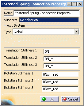
Click Fastened Spring Connection Property
 in the Connection Properties toolbar.
The Fastened Spring Connection Property dialog box appears.
-
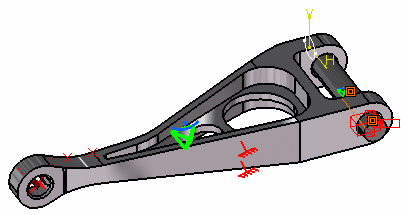
Select the assembly contact or coincidence constraint or joint body previously created in the Assembly Design workbench.
A symbol representing the Fastened Connection is visualized on the corresponding faces.
-
Enter the desired Translation and Rotation values.
In this particular example:
-
Enter 70N_m as Translation stiffness 2 value
-
Enter 70N_m as Translation stiffness 3 value.
-
-
Click OK.
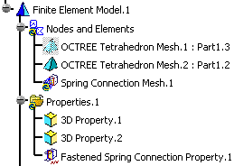
Note that two elements appear in the specification tree:
-
A Spring Connection Mesh.1 connection mesh part under the Nodes and Elements set,
-
A Fastened Spring Connection Property.1 connection property under the Properties.1 set.
-
-
The Finite Element Model contains two Mesh objects, one for each part of the assembly.
-
The sizes of the two meshes are different as can be seen by comparing the Mesh Size symbols.
![]()