This task shows you how to create a Finite Element Model, and optionally an Analysis Case.
Finite Element Models are representations used for performing computer-aided engineering analysis (CAEA) of products. They are complementary to computer-aided design (CAD) models, which are mainly geometric representations of products.
A Finite Element Model consists of:
- a system representation, consisting of:
- a Mesh objects set (containing Node and Element objects)
- a Properties objects set (containing Property-type objects)
- a Materials objects set (containing Material-type objects)
- an Axis objects set (containing Axis-type objects)
- various environment actions representations, each consisting
of:
- an Analysis Case object sets, defining implicitly the type of
analysis (solution procedure) expected, and possibly containing:
- a Restraints objects set (containing Restraint-type objects)
- a Loads objects set (containing Load-type objects)
- a (NS) Masses objects set (containing Mass-type objects)
- for each Analysis Case, a Solution objects set, defining the type
of results sought:
- images
- analyses
- reports
- graphs...
- an Analysis Case object sets, defining implicitly the type of
analysis (solution procedure) expected, and possibly containing:
The Finite Element Model can initiate a solution process when a sufficient amount of specifications have been captured in the objects constituting the representations of the model.
At the creation of a Finite Element Model, the program automatically generates the system representation template, and proposes to also generate an Analysis Case template for the environment representation and also for indicating the type of solution procedure sought.
If you do not have the ELFINI Structural Analysis product license, your Finite Element Model can simultaneously contain at most one Static Analysis Case and one Frequency Analysis Case.
Open the sample01.CATPart document from the samples directory.
-
Select Start > Analysis & Simulation > Generative Structural Analysis.
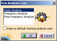
The New Analysis Case dialog box appears.

You can create several types of template:
- Static Analysis Case
- Frequency Analysis Case
- Free Frequency Analysis Case
-
Select the desired Analysis Case in the list.
The Finite Element Model specification tree template shows the standard system representation objects sets.
The Analysis Case representation contains the following empty object sets:
- Restraints
- Loads
- Masses
- Solution
- Sensors
-
Select the Keep As Default option in the New Analysis Case dialog box if you want to set the current choice as the default choice.
-
Click OK.
If you installed the ELFINI Structural Analysis (EST) product, the Finite Element Model can contain an arbitrary number of (Static and/or Frequency) Analysis Cases.