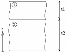
The purpose of this test is to check laminated plates with
orthotropic materials using an angle of orientation.
You will use 2D meshes.
Reference:
3D model with parabolic hexahedron elements (HE20), computed with CATIA.
 Specifications
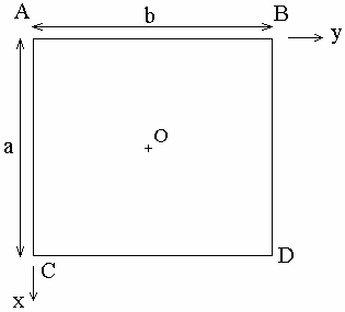
Geometry Specifications
|
Angle: |
|
|
a = 0.1 m |
|
|
|
|
Analysis Specifications
|
 |
|
|
|
Mesh Specifications:
|
|
|
Restraints (User defined):
|
|
|
Loads: |
 Results
The following results correspond to:
- The displacement of O along Z (w)
- The restraint on O in the center of plate 2 (
 xx)
xx)
|
|
3D model (Reference) |
2D model |
Normalized results |
|
w [mm] |
-3.47697 |
-3.47213 |
0.9986 |
|
|
30358.523 |
30217.189 |
0.9953 |
To Perform the Test:
The laminated_plates.CATAnalysis document presents a complete analysis of this case.
To compute the case, proceed as follow:
-
Open the CATAnalysis document.
-
Compute the case in the Generative Structural Analysis workbench.
-
Create local sensors (Stress tensor and Displacement vector).