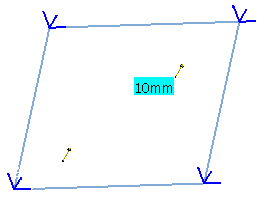
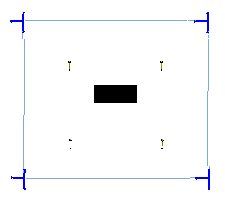
The purpose of this test is to validate orthotropic elements properties. You will use an isotropic biased plate and an orthotropic analog plate, computed with a 2D mesh.
Reference:
M. JONES, Mechanics of Composite Materials, Hemisphere publishing corporation, pp250-254, 1975.
ASHTON JE, An Analogy for Certain Anisotropic Plate, Journal of Composite Materials, pp355-358, April 1969.
 Specifications
Geometry Specifications
|
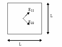
Isotropic biased plate:
|
|
|
Orthotropic analog plate:
|
|
Analysis Specifications
|
Isotropic plate:
|
|
|
Orthotropic plate:
|
|
|
Mesh Specifications: |
|
|
Restraints (User defined): |
|
 Results
- Analytical Solution:
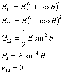
The following formula gives the analytical solution for the vertical displacement at the center of an isotropic biased plate:


This solution is also valid for an orthotropic plate with the geometry specifications indicated below, and with characteristics given by:
- Computed Results:
The computed results (in mm) are given in the tables below.
Normalized results (computed results divided by analytical solution) are listed.Plates
Analytical
SolutionLinear Triangle (TR3)
Parabolic Triangle (TR6)
Linear Quadrangle (QD4)
Parabolic Quadrangle (QD8)


Computed Results
Normalized
ResultsComputed Results
Normalized
ResultsComputed Results
Normalized
ResultsComputed Results
Normalized
ResultsBiased Isotropic
1.907
1.988
1.048
2.011
1.055
1.933
1.013
1.977
1.037
Analog Orthotropic
1.907
1.900
0.996
1.931
1.012
1.908
1.001
1.884
0.988
To Perform the Test:
The Isotropic_biased_plate_QD4.CATAnalysis document presents the complete analysis on an isotropic biased plate, computed with a mesh formed of linear quadrangle elements (QD4).
The Orthotropic_analog_plate_QD4.CATAnalysis document presents a complete analysis on an orthotropic analog plate, computed with a mesh formed of linear quadrangle elements (QD4).
To compute the case with other meshes (TR3, TR6 and QD8), proceed as follow:
-
Open one of the CATAnalysis documents.
-
In the Advanced Meshing Tools workbench, replace the mesh specifications as indicated above.
-
In the Generative Structural Analysis workbench, compute the case.
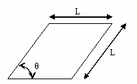 Isotropic
plate
 Orthotropic
plate