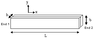
This test lets you check the bending/extension coupling in non-symmetric stack composite plates and the traverse shear behavior in a thick plate.
For this test, the reference is the mesh formed of linear hexahedron elements (HE8). You will use 2D meshes.
Reference:
3D Model with HE8 element, computed with CATIA.
 Specifications
Geometry Specifications
|
Length: |
|
|
Width: |
|
|
Thickness: |
Analysis Specifications
|
Material 1:
|
|
|
Material 2:
|
|
|
Mesh Specifications:
|
|
|
Restraints: |
|
|
Loads: |
 Results
The static analysis results correspond to the displacements Tx and Tz at End 2.
The buckling analysis is performed for this 30 N load case. The buckling coefficients for the lowest two modes, computed with CATIA, are presented in the table below:
|
Analysis Case |
Quantity |
Reference |
Computed Results |
|
|
Linear Quadrangle |
Parabolic Quadrangle |
|||
|
|
|
|
||
|
Static Case |
Tx max [mm] |
-0.027 |
-0.0277 |
-0.0281 |
|
Tz max [mm] |
-0.834 |
-0.834 |
-0.835 |
|
|
Buckling Case |
Coefficient 1 |
121.634 |
121.197 |
120.743 |
|
Coefficient 2 |
1126.56 |
1095.34 |
1079.94 |
|
To Perform the Test:
The Bonded_blades_compression_QD8.CATAnalysis document presents a complete analysis of this case, computed with a mesh formed of parabolic quadrangle elements (QD8).
The Bonded_blades_compression_HE8.CATAnalysis document presents a complete analysis of this case, computed with a mesh formed of linear hexahedron elements (HE8).
To compute the mesh with linear quadrangle elements (QD4), proceed as follow:
-
Open the Bonded_blades_compression_QD8.CATAnalysis document.
-
Enter the Advanced Meshing Tools workbench.
-
In the specification tree, double-click the mesh part. The Global Parameters dialog box appears.
-
Select Linear as element type.
-
Compute the case in the Generative Structural Analysis workbench.

