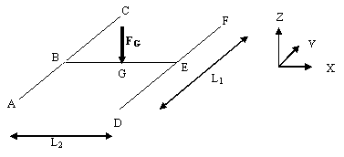
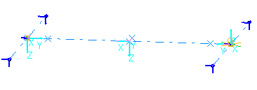
This test lets you check analysis results for a plane grid, in the context of an harmonic dynamic response case. You will use a 1D mesh.
This test is used to validate the following attributes:
-
1D beam elements
-
Harmonic dynamic response solve algorithms.
Reference:
AFNOR technique, SFM Paris, Guide de validation des progiciels de calcul de structures, SSLL 04/89, pp.198-199, 1990.
 Specifications
Geometry Specifications
|
Length: |
 |
|
Section IPE 200 :
|
|
|
The geometry is built with two Parts, inserted in a Product. The first Part includes the beam AC and the beam DF. The second Part includes the beam BE. |
Analysis Specifications
|
Young Modulus (material) |
|
|
Poisson's Ratio (material) |
|
|
Density: |
|
|
Mesh Specifications:
|
|
|
Restraints (User-defined):
|
|
|
Loads:
|
|
 Results
Frequency Response
|
Fundamental mode |
Frequency [Hz] |
Error [%] |
|
|
Analytical solution |
Computed results |
||
|
1 |
16.456 |
16.410 |
0.28 |
|
2 |
38.165 |
37.941 |
0.59 |
Harmonic Dynamic Response
Displacement on z axis at f = 12.7324 Hz
|
Point |
Type of values |
Analytical solution |
Computed results |
Error [%] |
|
B and E |
WBmax [mm] |
-98.00 |
-100.35 |
2.4 |
|
G |
WG+WGmax [mm] |
-227.00 |
-226.50 |
0.2 |
To Perform the Test:
The Harmonic_forced_vibrations_plane_grid.CATAnalysis document presents a complete analysis of this case.
Proceed as follow:
-
Open the CATAnalysis document.
-
Compute the case and generate an image called Deformed mesh.
