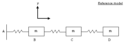
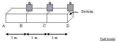
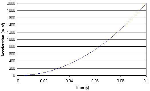
This test lets you check analysis results for a spring-mass system, in the context of a transient dynamic response case. You will use a 1D mesh.
This test is used to validate the following attributes:
-
1D beam element
-
Transient dynamic response solve algorithms.
Reference:
Guide de validation des prologiciels de calcul de structures, AFNOR Technique, SFM, pp182-183
 Specifications
Geometry Specifications
|
Mass: |
 |
| Stiffness: k = 1000 N_m |
|
|
Length: |
 |
| Section: area = 1.10-5 m2 |
Analysis Specifications
|
Young Modulus (material): |
|
|
Mesh Specifications: |
|
|
Restraints:
|
|
|
Loads:
|
 Results
Analytical Solution
The natural frequencies are the roots of the following equation:
![]()
The response at point D is given by:
![]()
with imposed acceleration coefficient:

and ![]() modal
participated factor for a translational motion with u = 1.
modal
participated factor for a translational motion with u = 1.
Frequency Analysis
|
Mode |
Frequencies [Hz] |
Error [%] |
|
|
Analytic solution |
Values |
||
|
1 |
2.239 |
2.2399 |
0.038 |
|
2 |
6.275 |
6.2760 |
0.015 |
|
3 |
9.069 |
9.0690 |
0 |
Transient Dynamic Analysis:
|
Time [s] |
Displacement [mm] |
Error [%] |
|
|
Analytic solution |
Values |
||
|
0.02 |
2.7 |
2.69 |
0.25 |
|
0.04 |
42.6 |
42.77 |
0.40 |
|
0.05 |
104.1 |
104.32 |
0.21 |
|
0.06 |
215.8 |
216.18 |
0.18 |
|
0.08 |
681.3 |
682.16 |
0.13 |
|
0.1 |
1658 |
1659.71 |
0.10 |
To Perform the Test:
The Transient_response_spring_mass_system.CATAnalysis document presents a complete analysis of this case.
Proceed as follow:
-
Open the CATAnalysis document.
-
Compute the case and generate an image called Deformed mesh.

