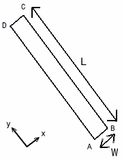
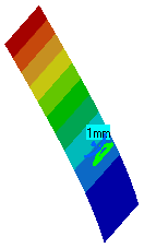
This test lets you compare analysis results for the buckling of a straight beam in CATIA with the Beam theory. In other words, you will study the quality of distorted membrane elements in a buckling analysis. You will use 2D meshes, with membrane elements.
Reference:
Beam Theory
 Specifications
Geometry Specifications
|
Length: |
|
|
Width: |
|
|
Thickness: |
Analysis Specifications
|
Young Modulus (material): |
|
|
Poisson's Ratio (material): |
|
|
Mesh Specifications:
|
|
|
Restraints: |
|
|
Loads: |
 Results
The critical load is given by column buckling theory:
![]()
In this particular case, the result is Nc = 35.53 N.
The results of the solver computation and the
normalized results (computed results divided by analytic solution) are
given in the table below.
|
|
Linear triangle shell |
Parabolic triangle shell |
Linear quadrangle shell |
Parabolic quadrangle shell |
||||
|
|
|
|
|
|||||
|
Mesh |
Regular |
Irregular |
Regular |
Irregular |
Regular |
Irregular |
Regular |
Irregular |
|
Computed buckling factor [N] |
317.435 |
287.831 |
35.483 |
35.537 |
36.135 |
47.478 |
35.221 |
35.272 |
|
Normalized Results |
8.934 |
8.101 |
0.999 |
1.000 |
1.017 |
1.336 |
0.991 |
0.993 |
To Perform the Test:
The Buckling_StraightBeam_in_plane.CATAnalysis document presents the complete analysis of the buckling case, computed with an irregular mesh formed of parabolic triangle elements (TR6).
To compute the case with linear triangle (TR3), linear quadrangle (QD4) and parabolic quadrangle (QD8) elements, open the Straight_Beam.CATPart document and proceed as follow:
-
Define the mesh using the Surface Meshing workshop in the Advanced Meshing Tools workbench.
-
In Generative Structural Analysis workbench, define analysis specifications as shown above.
-
Insert and compute buckling case solution in Generative Structural Analysis workbench.
To create an irregular mesh, use the Add/Remove Constraints icon in the Local Specifications toolbar, then select the points on the part.

