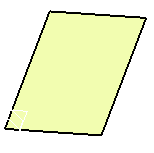
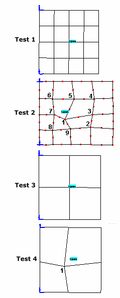
The purpose of this test is to check the distorted meshes. You will use 2D meshes formed of parabolic quadrangle elements (QD8).
Reference:
NAFEMS-Glasgow, Benchmark newsletter, April 1989, p.19.
 Specifications
Geometry Specifications
|
Length: |
 |
| Width: W = 10 m |
|
| Thickness: th = 0.05 m |
Analysis Specifications
|
Young Modulus (material): |
 |
|
Poisson's Ratio (material): |
|
|
Mesh Specifications:
|
|
|
Restraints (User-defined): Along y axis, Tx = Ty = Tz = Ry = 0 |
 Results
The results are given in the table below.
Normalized results (computed results divided by the reference solution) are
listed.
|
Mode |
Reference |
Test 1 |
Test 2 |
Test 3 |
Test 4 |
||||
|
Computed results |
Normalized results |
Computed results |
Normalized results |
Computed results |
Normalized results |
Computed results |
Normalized results |
||
|
1 |
0.421 |
0.419 |
0.995 |
0.420 |
0.998 |
0.419 |
0.995 |
0.420 |
0.998 |
|
2 |
1.029 |
1.023 |
0.994 |
1.032 |
1.003 |
1.024 |
0.995 |
1.028 |
0.999 |
|
3 |
2.582 |
2.576 |
0.998 |
2.606 |
1.009 |
2.697 |
1.045 |
2.703 |
1.047 |
|
4 |
3.306 |
3.295 |
0.997 |
3.317 |
1.003 |
3.420 |
1.034 |
3.540 |
1.071 |
|
5 |
3.753 |
3.733 |
0.995 |
3.930 |
1.047 |
3.900 |
1.039 |
3.993 |
1.064 |
|
6 |
6.555 |
6.841 |
1.044 |
6.799 |
1.037 |
6.677 |
1.019 |
6.844 |
1.044 |
To Perform the Test:
The cantilever_thin_square_plate_test2.CATAnalysis document presents a complete analysis of the test 2, computed with an irregular mesh formed of parabolic quadrangle elements (QD8).
To compute the three other tests, with other nodes of distribution, proceed as follow:
-
Open the CATAnalysis document.
-
In the Advanced Meshing Tools workbench, change the mesh specifications as indicated above.
-
Compute the case in the Generative Structural Analysis workbench.