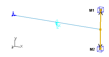
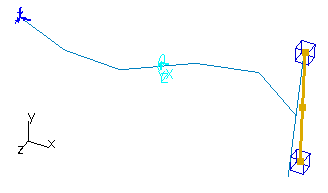
The purpose of this test is to check the coupling between torsional and flexural behavior. You will use a 1D beam.
Reference:
NAFEMS-Glasgow, Benchmark newsletter, p.15, April 1989.
 Specifications
Geometry Specifications
|
Length: |
 |
|
Section (circular): |
|
|
Mass 1 (center):
|
|
|
Mass 2 (center):
|
Analysis Specifications
|
Young Modulus (material): |
|
|
Poisson's Ratio (material): |
|
|
Mesh Specifications:
|
|
|
Restraints (User-defined): |
 Results
The results are based on the 6 lowest normal modes of the
structure.
The results and the percentage of errors are listed in the table below:
|
Mode |
Exact [Hz] |
Beam [Hz] |
Error [%] |
|
1 |
1.723 |
1.722 |
0.058 |
|
2 |
1.727 |
1.725 |
0.116 |
|
3 |
7.413 |
7.410 |
0.040 |
|
4 |
9.972 |
9.946 |
0.261 |
|
5 |
18.160 |
18.046 |
0.628 |
|
6 |
26.972 |
26.697 |
1.020 |
To Perform the Test:
The cantilever_beam_excentric_point_masses.CATAnalysis document presents a complete analysis of this case, computed with a mesh formed of beam elements. Proceed as follow:
-
Open the CATAnalysis document.
-
Compute the case and generate an image called Deformed mesh.
