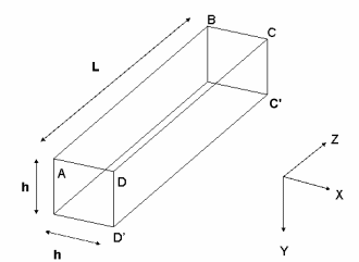
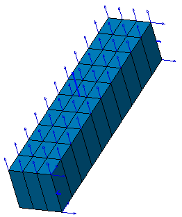
This test lets you check modal analysis results for a beam with 3D meshes formed of linear or parabolic hexahedron elements.
Reference:
ABBASSIAN F., Dawswell D.J., Knowles N.C., NAFEMS-Glasgow, Free Vibrations Benchmarks, pp438-452, November 1987.
 Specifications
Geometry Specifications
|
Length: |
 |
|
Width and Height: |
Analysis Specifications
|
Young Modulus (material): |
 |
|
Poisson's Ratio (material): |
|
|
Density: |
|
|
Mesh specifications:
|
|
|
Restraints (User-defined):
|
 Results
The results of the test are presented in the table below:
|
Mode |
Reference solution |
Parabolic hexahedron (HE20) |
Linear hexahedron (HE8) |
||
|
|
|
||||
|
Frequencies |
Normalized |
Frequencies |
Normalized |
||
|
1 |
38.2 |
38.27 |
1.002 |
38.28 |
1.002 |
|
2 |
85.21 |
87.67 |
1.029 |
83.95 |
0.985 |
|
3 |
152.23 |
157.5 |
1.035 |
157.57 |
1.035 |
|
4 |
245.53 |
259.01 |
1.055 |
264.92 |
1.079 |
|
5 |
297.05 |
306.06 |
1.030 |
298.33 |
1.004 |
To Perform the Test:
The Deep_simply_supported_solid_beam_HE8.CATAnalysis document presents a complete analysis of this case, computed with a mesh formed of linear hexahedron elements (HE8).
To compute the analysis with parabolic hexahedron elements (HE20), open the Deep_simply_supported_solid_beam.CATPart document, and proceed as follow:
-
Define the mesh for the 2D surface presented in the CATPart document, using the Surface Meshing workshop in the Advanced Meshing Tools workbench.
-
Extrude the mesh to obtain a 3D mesh.
-
Define analysis specifications as indicated below.
-
Compute the CATAnalysis and generate an image called Deformed mesh.
For a 3D hexahedron mesh, you need to create a mesh on a 2D part, then to extrude it with the Extrude Mesher in Translation icon, in the Advanced Meshing Tools workbench.