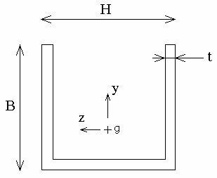
The purpose of this test is to take into account the center of torsion.
The type of test is a 1D model, non symmetric section with center of
torsion, different from the center of gravity. Both predefine sections (Thin
U-Beam) and define from a surface sections (Beam from surface) are used.
Reference:
Modélisation des structures par éléments finis, BATOZ J.L., DHATT G., Vol.2; Hermès Edition, Paris 1990.
 Specifications
Geometry Specifications
 |
|
|
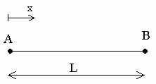
L = 0.1 m |
Analysis Specifications
| Young Modulus (material): E = 200 GPa |
 |
|
Poisson's Ratio (material): |
|
|
Mesh Specifications:
|
|
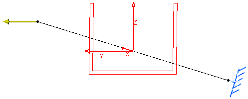
| Restraints: Clamp on A |
|
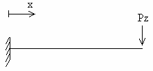
| Loads (Distributed force): On B: Pz = 1N |
 Results
Analytical Solution
 |
 |
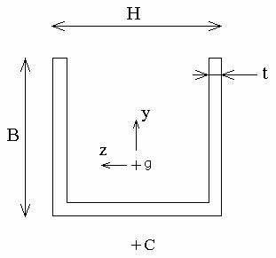
- g: center of gravity
- C: center of torsion/shearing. C is the point of the section where
shearing restraints due to a cutting effort generate a null moment of torsion.
The rotation of the section on x is given by:

where: - G: shearing coefficient (Pa)
For an isotropic material:

- J: Inertia/Constant of torsion (m4)
For a U-Beam section (valid formula for t < B and H):

- Mx: moment of torsion (N.m)

- yc: coordinates of point C on y (the origin of the axis
system is the center of gravity)
For a U-Beam section:

- G: shearing coefficient (Pa)
For:
J = 0.5376 x 10⁻¹² m4
yc = -5.65046 x 10⁻³ m
x = L
The result of the analytic solution is:
![]() = -1.33063 x 10⁻² rad
= -1.33063 x 10⁻² rad
Computed results
|
Results |
Reference |
Case 1 "Thin U-beam" |
Case 2 "Beam from surface" |
|
|
-1.33063 x 10⁻² |
-1.33063 x 10⁻² |
-1.35608 x 10⁻² |
|
Normalized results |
1 |
1 |
1.019 |
To Perform the Test:
The thin_u_beam.CATAnalysis document presents a complete analysis of this case.
To compute the case, proceed as follow:
-
Open the CATAnalysis document.
-
Compute the case in the Generative Structural Analysis workbench.
-
Create a local sensor (Rotation vector).
