This test is used to study the convergence and the absence
of any locking in the case of very thin shells (th / L = 0.5e-4).
You will use 2D meshes.
Reference:
TIMOSHENKO S.P., WOINOWSKY-KRIGER S., Theory of Plates and Shells, 1959.
 Specifications
Geometry Specifications
|
Length: |
|
|
Thickness: |
|
|
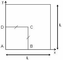
For symmetry reasons, only a quarter of the plate is modeled (ABCD). |
Analysis Specifications
|
Young Modulus (material): |
|
|
Poisson's Ratio (material): |
|
|
Mesh Specifications: |
|
|
Restraints (User-defined):
|
|
|
Loads:
|
|
 Results
-
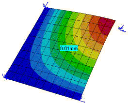
The analytical solutions for the z displacement of the point C are:
Case 1: Tz=64.96 mm
Case 2: Tz=90.942 mm -
The tables below present the analysis results for cases 1 and 2.
The normalized results (computed results divided by analytical solution) are listed.-
Case 1:
Nodes
Analytical solution
[mm]Values
Linear triangle
(TR3)Parabolic triangle
(TR6)Linear quadrangle
(QD4)Parabolic quadrangle
(QD8)


Computed results
[mm]Normalized results
Computed results
[mm]Normalized results
Computed results
[mm]Normalized results
Computed results
[mm]Normalized results
3 x 3
64.96
62.15
0.957
62.09
0.956
67.44
1.038
63.03
0.970
5 x 5
64.96
64.66
0.995
64.61
0.995
66.37
1.022
64.58
0.994
7 x 7
64.96
64.81
0.998
64.83
0.998
65.77
1.013
64.80
0.997
9 x 9
64.96
64.87
0.999
64.89
0.999
65.49
1.008
64.87
0.999
11 x 11
64.96
64.91
0.999
64.92
0.999
65.33
1.006
64.91
0.999
-
Case 2:
Nodes
Analytical solution
[mm]Values
Linear triangle
(TR3)Parabolic triangle
(TR6)Linear quadrangle
(QD4)Parabolic quadrangle
(QD8)


Computed results
[mm]Normalized results
Computed results
[mm]Normalized results
Computed results
[mm]Normalized results
Computed results
[mm]Normalized results
3 x 3
90.942
83.621
0.919
87.039
0.957
90.308
0.993
86.767
0.987
5 x 5
90.942
89.196
0.981
91.117
1.002
91.576
1.007
90.977
1.000
7 x 7
90.942
90.276
0.993
91.053
1.001
91.366
1.005
90.998
1.001
9 x 9
90.942
90.596
0.996
91.030
1.001
91.231
1.003
90.998
1.001
11 x 11
90.942
90.746
0.998
91.019
1.001
91.155
1.002
90.998
1.001
-
To Perform the Test:
The simplysupportedplate11nodesqd8.CATAnalysis document presents a complete analysis of this case, computed with a mesh formed of 11 nodes and parabolic quadrangle elements (QD8).
To compute the case with other types of elements and other number of nodes, proceed as follow:
-
Open the CATAnalysis document.
-
In the Advanced Meshing Tools workbench, change the mesh specifications as indicated above.
-
Compute the case in the Generative Structural Analysis workbench.

