The purpose of this test is to check membrane elements. You will use 2D meshes.
Reference:
M. ZIENKIEWICKZ, The Finite Element Method, 4th edition, Vol. 1, p.386.
 Specifications
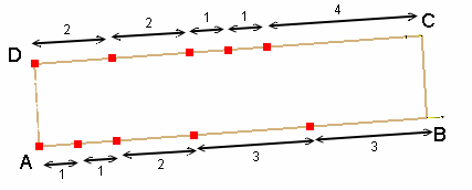
Geometry Specifications
|
Length: |
|
|
Width = |
|
|
Thickness: |
Analysis Specifications
|
Young Modulus (material): |
|
|
Poisson's Ratio (material): |
|
|
Mesh Specifications:
|
|
|
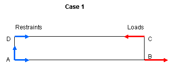
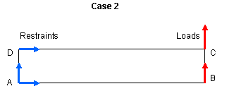
Restraints (User-defined):
|
|
|
Loads (Distributed force):
|
|
 Results
-
The analytical solution is the vertical displacement at point B. The corresponding analytical solutions are:
Case 1: Ty = 100.00 mm
Case 2: Ty = 102.60 mm -
The table below presents the analysis results.
The results correspond to the vertical displacement at point B.
The normalized results (computed results divided by analytical solution) are listed.Analytical solution [mm]
Values
Linear triangle
(TR3)Parabolic triangle
(TR6)Linear quadrangle
(QD4)Parabolic quadrangle
(QD8)


Computed results
[mm]Normalized results
Computed results
[mm]Normalized results
Computed results
[mm]Normalized results
Computed results
[mm]Normalized results
Case 1
100
25.49
0.255
100
1.000
96.18
0.962
100
1.000
Case 2
102.6
29.78
0.290
101.54
0.989
98.05
0.956
102.8
1.002
To Perform the Test:
The thick_beam_qd8.CATAnalysis document presents a complete analysis of this case, computed with a mesh formed of parabolic quadrangle elements (QD8).
To compute the case with other types of elements, proceed as follow:
-
Open the CATAnalysis document.
-
In the Advanced Meshing Tools workbench, change the mesh specifications as indicated above.
-
Compute the case in the Generative Structural Analysis workbench.