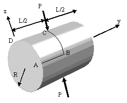
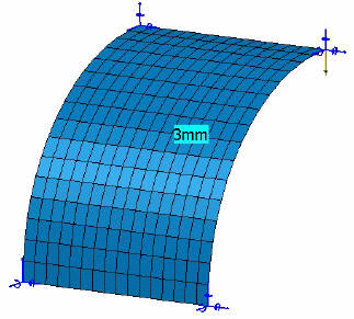
The purpose of this test is to check shell elements. You will use 2D meshes.
Reference:
LINBERG G.M., OLSON M.D., New Developments in the Finite Element Analysis of Shells, COXP. Mech. Eng. and Nat. Aeronautical Establishment, National Research Council of Canada Vol. 4., 1969
 Specifications
Geometry Specifications
|
Length: |
|
|
Radius: |
|
|
Thickness: |
|
|
For symmetry reasons, only 1/8 of the body is modeled. The given results are the same for 1/8 or for the whole body. |
Analysis Specifications
|
Young Modulus (material): |
|
|
Poisson's Ratio (material): |
|
|
Mesh Specifications: Imposed nodes on AB, BC, CD, DA |
|
|
Restraints:
|
|
|
Loads (Distributed force): F = 0.25 inward at C |
 Results
-
The theoretical value of the radial displacement at the point load location is 18.25 mm.
-
The results correspond to the radial displacement at point C.
The table below presents the analysis results.
Normalized results (computed results divided by analytical solution) are listed.
|
Nodes |
Values |
|||||||
|
Linear triangle |
Parabolic triangle |
Linear quadrangle |
Parabolic quadrangle |
|||||
|
|
|
|
|
|||||
|
Computed results |
Normalized results |
Computed results |
Normalized results |
Computed results |
Normalized results |
Computed results |
Normalized results |
|
|
3 x 3 |
0.98 |
0.054 |
8.19 |
0.449 |
1.73 |
0.095 |
12.07 |
0.662 |
|
5 x 5 |
8.13 |
0.445 |
13.38 |
0.733 |
10.09 |
0.551 |
16.43 |
0.901 |
|
7 x 7 |
13.28 |
0.728 |
19.12 |
1.047 |
14.00 |
0.767 |
17.29 |
0.948 |
|
9 x 9 |
15.95 |
0.874 |
19.98 |
1.095 |
16.34 |
0.895 |
18.17 |
0.996 |
|
11 x 11 |
15.87 |
0.870 |
17.10 |
0.937 |
17.04 |
0.934 |
17.97 |
0.985 |
|
13 x 13 |
17.09 |
0.936 |
18.91 |
1.036 |
17.42 |
0.955 |
17.81 |
0.976 |
|
15 x 15 |
16.87 |
0.924 |
17.56 |
0.962 |
17.86 |
0.978 |
18.08 |
0.991 |
|
17 x 17 |
17.19 |
0.942 |
17.82 |
0.976 |
18.09 |
0.991 |
18.33 |
1.004 |
To Perform the Test:
The pinched_cylinder_17nodes_qd8.CATAnalysis document presents a complete analysis of this case, computed with a mesh formed of parabolic quadrangle elements (QD8).
To compute the case with other types of elements and number of nodes, proceed as follow:
-
Open the CATAnalysis document.
-
In the Advanced Meshing Tools workbench, change the mesh specifications as indicated above.
-
Compute the case in the Generative Structural Analysis workbench.

