The purpose of this test is to check shell elements with double curvature. You will use 2D meshes.
Reference:
MAC NEAL R.H., HARDER R.L., A Proposed Standard Set of Problems to Test Finite Element Accuracy, Finite Element Design, Vol.1, pp.3-20, 1985.
 Specifications
Geometry Specifications
|
Radius: |
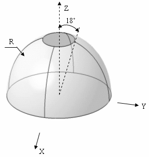 |
| Angle: θ = 18 deg |
|
|
Thickness: |
|
|
Equation: |
|
|
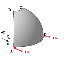
For symmetry reasons, only a quarter of the hemisphere is modeled. The given results are the same for a quarter or for the whole hemisphere. |
Analysis Specifications
|
Young Modulus (material): |
|
|
Poisson's Ratio (material): |
|
|
Mesh Specifications:
See the values in the table of results. |
|
|
Restraints (User-defined):
|
|
|
Loads (Distributed force): F=1 (outward at A, inward at D) |
 Results
-
The analytical solution is:
At point A, x-displacement is 94 mm. -
The results correspond to the x-displacements at point A.
The table below presents the analysis results.
The normalized results (computed results divided by analytical solution) are listed.
|
Nodes |
Values |
|||||||
|
Linear |
Parabolic |
Linear |
Parabolic |
|||||
|
|
|
|
|
|||||
|
Computed results |
Normalized results |
Computed results |
Normalized results |
Computed results |
Normalized results |
Computed results |
Normalized results |
|
|
3 x 3 |
105.9 |
1.127 |
99.97 |
1.063 |
71.17 |
0.757 |
23.00 |
0.245 |
|
5 x 5 |
98.02 |
1.043 |
100.46 |
1.069 |
96.05 |
1.022 |
79.25 |
0.843 |
|
7 x 7 |
95.76 |
1.019 |
101.95 |
1.085 |
96.47 |
1.026 |
94.75 |
1.008 |
|
9 x 9 |
94.85 |
1.009 |
102.26 |
1.088 |
95.48 |
1.016 |
95.52 |
1.016 |
|
11 x 11 |
94.97 |
1.010 |
103.75 |
1.104 |
94.80 |
1.009 |
94.52 |
1.006 |
|
13 x 13 |
93.32 |
0.993 |
101.87 |
1.084 |
93.90 |
0.999 |
93.68 |
0.997 |
To Perform the Test:
The hemispherical_shell_concentrated_loads_13nodes_tr6.CATAnalysis document presents a complete analysis of this case, computed with a mesh formed of parabolic triangle elements (TR6).
The hemispherical_shell_concentrated_loads_13nodes_qd8.CATAnalysis document presents a complete analysis of this case, computed with a mesh formed of parabolic quadrangle elements (QD8).
To compute the case with other types of elements and number of nodes, proceed as follow:
-
Open one of the CATAnalysis documents.
-
Enter the Advanced Meshing Tools workbench.
-
In the specification tree, double-click on the mesh.
The Global Parameters dialog box appears.
-
Select the Linear element type.
-
Compute the case in the Generative Structural Analysis workbench.