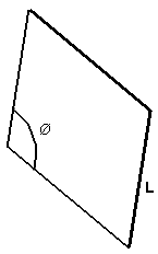
The purpose of this test is to evaluate the sensitivity of a plate element to the direction (angular orientation) of the mesh on a plate in bending, in a context of a static case. You will use 2D meshes.
Reference:
- MORLEY L.S.D., Skew Plates and Structures, Pergamon Oxford 1963.
- RAZZAQUE A., Program for Triangular Bending Elements with Derivative Smoothing, IJNME Vol 6, pp333-343, 1973.
 Specifications
Geometry Specifications
|
Length: |
|
|
Thickness: |
|
|
Angle: |
Analysis Specifications
|
Young Modulus (material): |
|
|
Poisson's ratio (material): |
|
|
Restraints (User-defined): |
|
|
Loads: |
 Results
The vertical displacements at the center for various mesh directions are given in the following tables.
Output Results (7 x 7 nodes)
|
Angle |
Theoretical value [mm] |
Computed value [mm] |
|||
|
Linear triangle |
Parabolic triangle |
Linear quadrangle |
Parabolic quadrangle |
||
|
|
|
|
|
||
|
80 deg |
1.409 x 10⁻³ |
1.359 x 10⁻³ |
1.414 x 10⁻³ |
1.42 x 10⁻³ |
1.425 x 10⁻³ |
|
60 deg |
0.9318 x 10⁻³ |
0.925 x 10⁻³ |
0.9334 x 10⁻³ |
0.935 x 10⁻³ |
0.901 x 10⁻³ |
|
40 deg |
0.3487 x 10⁻³ |
0.3455 x 10⁻³ |
0.3592 x 10⁻³ |
0.3538 x 10⁻³ |
0.2923 x 10⁻³ |
|
30 deg |
0.1485 x 10⁻³ |
0.1474 x 10⁻³ |
0.1483 x 10⁻³ |
0.1538 x 10⁻³ |
0.1106 x 10⁻³ |
Output results (13 x 13 nodes)
|
Angle |
Theoretical value |
Computed value [mm] |
|||
|
Linear triangle |
Parabolic triangle |
Linear quadrangle |
Parabolic quadrangle |
||
|
|
|
|
|
||
|
80 deg |
1.409 x 10⁻³ |
1.409 x 10⁻³ |
1.431 x 10⁻³ |
1.422 x 10⁻³ |
1.422 x 10⁻³ |
|
60 deg |
0.9318 x 10⁻³ |
0.9403 x 10⁻³ |
0.9412 x 10⁻³ |
0.937 x 10⁻³ |
0.9306 x 10⁻³ |
|
40 deg |
0.3487 x 10⁻³ |
0.3566 x 10⁻³ |
0.3558 x 10⁻³ |
0.3493 x 10⁻³ |
0.3271 x 10⁻³ |
|
30 deg |
0.1485 x 10⁻³ |
0.153 x 10⁻³ |
0.1537 x 10⁻³ |
0.1497 x 10⁻³ |
0.1307 x 10⁻³ |
To Perform the Test:
The Morley_60degree_TR6_7nodes.CATAnalysis document presents a complete analysis of this case, computed with a mesh formed of 7 nodes per edge and parabolic triangle elements (TR6).
The Morley_80degree_QD8_13nodes.CATAnalysis document presents a complete analysis of this case, computed with a mesh formed of 13 nodes per edge and parabolic quadrangle elements (QD8).
To compute cases with other element types, angular orientation, and number of nodes, proceed as follow:
-
Open one of the CATAnalysis documents.
-
In the Advanced Meshing Tools workbench, replace the mesh specifications as indicated above.
-
In the Generative Structural Analysis workbench, compute the case.

