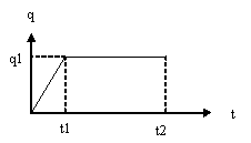
This test lets you check analysis results for a beam with different
inertia, in the context of a transient dynamic response case. You will use
a 1D mesh.
This test proposed by AFNOR is used to validate the transient dynamic
response solve algorithms.
Reference:
Guide de validation des prologiciels de calcul de structures, AFNOR Technique, SFM pp188-189.
 Specifications
Geometry Specifications
|
Beams AC and DB:
|
|
|
Beams CD:
|
|
|
The structure and the load being symmetrical, only one half of the beam is modeled. |
|
Analysis Specifications
|
Young Modulus (material): |
|
|
Masses for Frequency Case:
|
|
|
Mesh Specifications: |
|
|
Restraints:
|
|
|
Loads:
|
|
 Results
Frequency Response
|
Bending mode |
Frequency [Hz] |
Error [%] |
|
|
Analytical solution |
Computed results |
||
|
1 |
63.009 |
62.8796 |
0.21 |
Transient Dynamic Response
|
Time [s] |
Point |
Displacement V [mm] |
Error [%] |
|
|
Analytical Solution |
Computed results |
|||
|
0.0595 |
2437.5 |
2.469 |
2.467 |
0.09 |
To Perform the Test:
The Transient_dynamic_response_beam_inertia.CATAnalysis document presents the complete analysis of the transient dynamic response case.
To compute the case, proceed as follow:
-
Open the CATAnalysis document.
-
Compute the Frequency case, and generate an image called Deformed mesh.

