![]()
Open a document containing schematic components and cables already routed.
![]()
-
Click the Wires Management
 button.
 -
Select the cable for which you want to define connectivity.
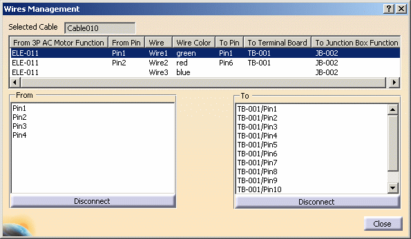
The Wires Management dialog box opens: 
- The Selected Cable field shows the reference designator of the cable selected.
- The first column shows the part from which the cable is routed, in this case a motor.
- The From Pin column displays the pin from which it is routed.
- The Wire column column shows the wire in the cable that is connected to the pin.
- The Wire Color column gives the wire color.
- The To Pin column shows the pin to which it is connected.
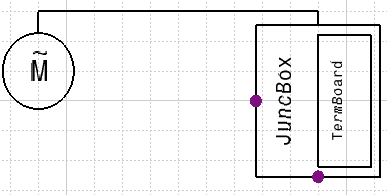
- The next column displays the part to which it is routed, in this case a terminal board. If there are no further connections there will be no more columns. In the example above there is another column because the terminal board is connected to a junction box.
-
In the example above two of the wires (green and red) are connected. To connect a wire, select it, and then select the From and To pins.
-
To disconnect a pin, selecting the wire, and click the Disconnect button. Clicking the Disconnect button below the From list will disconnect the From pin, beneath the To list it will disconnect the To pin.
-
Click Close when you are done.
