This methodology explains how to use a back shell as a
guiding support:
A back shell is usually connected to a connector through a back shell
connection point and to a bundle segment through a bundle connection point.
Adding a support function to this back shell allows a bundle segment to go
through this device to the connector, from the back shell connection point
to the support position point, getting an accurate geometry.
This object will be used as a back shell to be placed in the 3D, but as it
has support position points, it will also be recognized as a support for
bundle segment routing.
To do so, the part will be defined as a back shell. This back shell gets
both a back shell connection point (for automatic placement to the
connector) and support points and planes to be used as support. No bundle
connection point on the back shell will be used for routing.
Creating the Back Shell
![]()
-
In the Electrical Part Design workbench, click Define Back Shell
 to add back shell behavior to this part.
 -
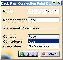
Click Define Back Shell Connection Point
 to add a connection point to the device. It will be used to correct
position the back shell during connection to the connector.
To do so:-
Select the outer face as Representation and Contact constraint
-
Select the hole axis as Coincidence constraint, and then click OK.

-
-
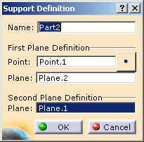
Click Define Support Part
 to add the position point and planes. These geometries will be used as
support entry and exit points.
To do so:-
Select the point: Point.1
-
Select the planes: Plane.2 and Plane.1.

-
The device is ready to use.
Using the Device
![]()
-
Click Connect Electrical Devices
 .
Thanks to the definition of the back shell connection point on the back
shell and on the connector, the placement and connection of these two
devices will be done automatically.
 -
Select the back shell then the connector.

They are connected. 
-
Switch to the Electrical Harness Assembly workbench to define a branchable bundle segment.
-
Click Multi-Branchable Document
 .
.
The dialog box opens. -
Define the bundle segment parameters and click Route Definition.
-
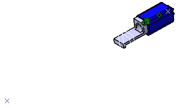
Select the point (Point.1), the back shell (Part.2, note that it is considered as a support) then the connector (Single connector DF56L, which has the bundle connection point).

The bundle segment definition takes into account the accurate length needed to go through the back shell to the connector, as well as the exact geometry according to the routing constraints. Moreover, the bundle segment is visualized up to the connector (and not only to the bundle connection point as is the case with a plain back shell.)