![]()
-
Click Connect Electrical Devices
 to connect the two single insert connectors.
You are prompted to select a connector. -
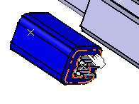
Select the connector connection point of SingleConnectorDF56R that is represented by the front face as shown below:
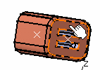
You are prompted to select another connector.
-
Select the connector connection point of SingleConnectorDF56L that is represented by the front face as shown below:
The connectors are connected together. 
- An electrical connection has been created to reflect the fact that the connectors are electrically connected.
- Using the definition of the connector connection points, mechanical constraints are created to ensure correct positioning.
- It is the first object selected that moves to the location of the second object.
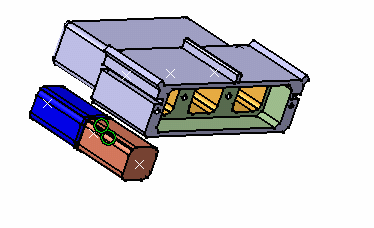
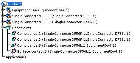
The mechanical constraints are added to the specification tree: 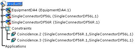
-
Click Connect Electrical Devices
 again to place SingleConnectorDF56L in the first cavity of
the equipment.
You are prompted to select a connector. -
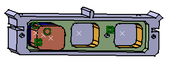
Select the cavity connection point of SingleConnectorDF56L that is represented by the face as shown below:
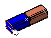
You are prompted to select another connector. -
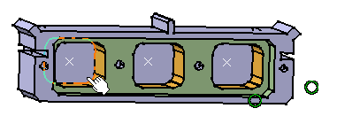
Select the cavity connection point of EquipmentDA4 that is represented by the face as shown below:
